Tx back channel adaptation algorithm

Active Publication Date: 2010-07-15
AVAGO TECH INT SALES PTE LTD
View PDF13 Cites 69 Cited by
  • Summary
  • Abstract
  • Description
  • Claims
  • Application Information

AI Technical Summary

Benefits of technology

[0003]An embodiment of the present invention may comprise a method to adapt coefficients of taps of a Finite Impulse Response (FIR) filter to increase elimination of interference from a digital communications signal comprising: transmitting the digital communications signal on a communications channel; eliminating at a least a portion of interference introduced into the digital communications signal by passing the digital communications signal through the Finite Impulse Response (FIR) filter to create a FIR filtered signal, the FIR filter having at least one pre/post cursor tap that has a pre/post cursor tap coefficient; passing the FIR filtered signal over the communications channel causing the FIR filtered signal to be distorted by the interference to create a received signal that is passed to a quantifier as a quantifier input signal; qu

Problems solved by technology

Typical real-world communications channels are limited such that a signal pulse frequency cannot exceed a particular high frequ

Method used


Image

  • Tx back channel adaptation algorithm
  • Tx back channel adaptation algorithm
  • Tx back channel adaptation algorithm

Examples


Embodiment Construction

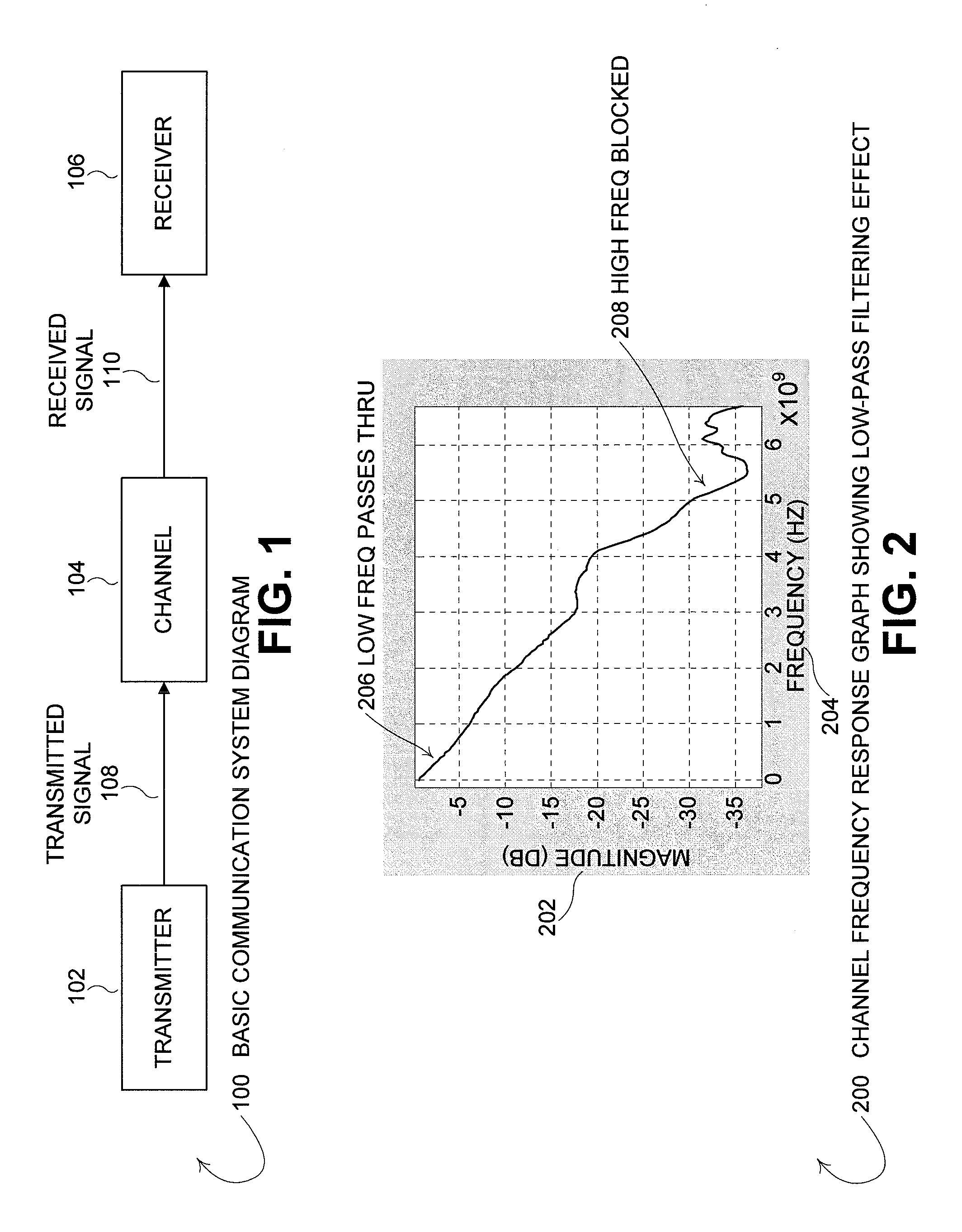
[0023]FIG. 1 is a diagram of a basic communication system 100. In a basic communications system 100, a transmitter 102 sends a signal 108 over a communications channel 104 to a receiver 106. The communications channel 104 (aka. communication medium) in an ideal system does not distort the signal 108, so the received signal 110 is equal to the transmitted signal 108. For a digital communications system, the signal 108, 110 is comprised of a series of pulses. For an ideal channel 104, the transmitter 102 sends pulses of perfect square waves, which are not distorted by the ideal channel 104 and are read / decoded by the receiver 106 without errors. For the ideal system there is a flat gain over the frequency domain, implying an infinite frequency bandwidth for the ideal channel 104. In a real-world, practical communications system 100, the received signal 110 is corrupted and / or distorted by the physical communications mediums that make up the communications channel 104. Common non-ideal...


PUM


Abstract

Disclosed is a method and system that adapts coefficients of taps of a Finite Impulse Response (FIR) filter to increase elimination of Inter-Symbol Interference (ISI) introduced into a digital communications signal due to distortion characteristics caused by a real-world communications channel. In the communications system there is a Finite Impulse Response (FIR) filter. The FIR filter has at least one pre and/or post cursor tap that removes pre and/or post cursor ISI from the signal, respectively. The pre/post cursor taps each have pre/post cursor coefficients, respectively, that adjusts the effect of the pre/post cursor portion of the FIR filter. The FIR filtered signal is transmitted over the channel which distorts the signal due to the changing and/or static distortion characteristics of the channel. The channel distorted signal is received at a receiver that may pass the channel distorted signal through a quantifier/decision system (e.g., a slicer) as the quantifier input signal to quantify the quantifier input signal to one of multiple digital values. The channel distorted signal may be further adjusted by summing the channel distorted signal with the output of a Decision Feedback Equalizer (DFE) filter to create a DFE corrected signal which then becomes the quantifier input signal. An error signal is determined by finding the difference between the scaled quantifier decision and the quantifier input signal. The pre/post cursor coefficient values that adjust the effects of the pre/post cursor taps of the FIR filter are updated as a function of the error signal and at least two quantifier decision values, and update coefficient values, may be sent over a communications back-channel to the FIR filter.

Description

BACKGROUND OF THE INVENTION[0001]A digital communications system sends data bits from one location, a transmitting location, to another location, a receiving location. Typically a digital communications system utilizes a transmitter located at the transmitting location to transmit a digital communications signal across a physical communication medium (aka. a communications channel) to a receiver located at the receiving location. The digital communications signal is typically made up of a series of voltage pulses of multiple different voltage levels measured at equal time periods (aka. equal time slices). In practice, a voltage level is based on a voltage range. For instance, a “target voltage” may be at the center of a voltage range, but any voltage between the minimum voltage and maximum voltage of the range is interpreted to be the “target voltage.” As an example, for a binary digital voltage system, a first voltage level represents a first digital value and a second voltage valu...

Claims


Application Information

Patent Timeline
IPC IPC(8): H03H7/40
CPCH04L25/03343H04L25/03057
Inventor MALIPATIL, AMARESHZHONG, LIZHIJIN, WENYILIU, YE
Owner AVAGO TECH INT SALES PTE LTD
Why Eureka
Try Eureka