Airborne reconnaissance system

a reconnaissance system and airborne technology, applied in the direction of speed/acceleration measurement, navigation instruments, instruments, etc., can solve the problems of significantly increasing flying costs and risks, length of time required for film development, and inability to tolerate, so as to and improve the measurement of array orientation.

Active Publication Date: 2005-08-11
THE STATE OF ISRAEL MINIST OF AGRI & RURAL DEV AGRI RES ORG ARO VOLCANI CENT
View PDF19 Cites 59 Cited by
  • Summary
  • Abstract
  • Description
  • Claims
  • Application Information

AI Technical Summary

Benefits of technology

[0061] Preferably, at least some of the sensors of the Inertial Navigation System are positioned on the gimbals, for improving the measuring of the orientation of the array with respect to the selective area portion.
[0062] Preferably, at least some of the light sensitive sensors are positioned on the gimbals, for improving the measuring of the orientation of the Line Of Sight with respect to the selective area portion.
[0063]...

Problems solved by technology

The main problem of the airborne, film-camera based reconnaissance system is the length of time required for developing the film, an operation that can be performed only after landing.
The need for securing the reconnaissance aircraft, while flying above or close to hostile areas has significantly increased flying costs and risks, as sometimes the reconnaissance mission requires escorting of the aircraft by other, fighter aircrafts.
There are several other problems generally involved in carrying out airborne reconnaissance.
A significant problem which is characteristic of the prior art reconnaissance systems, particularly said electronically scanning Across-Track and Along-Track scanning methods, is the need for predefining for the aircraft an essentially straight scanning leg (and generally a plurality of such parallel straight legs), and once such a leg is defined, any deviation, particularly a rapid or large deviation, from the predefined leg, is not tolerated, as said systems of the prior art are not capable of maintaining a desired line of sight direction during such a fast and/or large deviation from the predefined leg, resulting in image artifacts such as tearing (dislocation of image lines), smearing (elongation of pixels) or substantial gaps in the image information.
This is particularly a significant drawback when carrying out a reconnaissance mission above or close to a hostile area, when the need arises for the aircraft to carry out fast maneuvering to escape enemy detection or targeting.
However, in most cases the reconnaissance systems of the prior art cannot tolerate carrying out such a sharply curved maneuvering, involving sharp changes in the angles of the line of sight with respect to the photographed scenery.
Another drawback characteristic of the reconnaissance systems of the prior art, for example, U.S. Pat. No. 5,155,597, U.S. Pat. No. 5,692,062, WO 97/42659, and U.S. Pat. No. 6,256,057, is their need to handle vast amounts of data.
The systems of the prior art do not enable an easy, selective imaging of small portions of an area of interest.
Another particular problem which evolves from this limitation is the need for distinguishing and decoding a small data of interest within the said full, huge amount of data obtained.
Still another drawback of reconnaissance systems of the prior art, for example, U.S. Pat. No. 5,155,597, U.S. Pat. No. 5,692,062, WO 97/42659, U.S. Pat. No. 6,130,705, and U.S. Pat. No. 6,256,057 is their limited ability to capture images in a wide range of a fiel...

Method used


Image

  • Airborne reconnaissance system
  • Airborne reconnaissance system
  • Airborne reconnaissance system

Examples


example 1

[0128] The following is a numeric example for assessing the pixels smear in the prior art systems when capturing a terrain with large variations, showing a forward oblique scenario: Aircraft flying at a velocity of 250 m / s, range from the aircraft to scene of 10 km to level ground, exposure time of 10 ms, and assuming mountain 757 is at ½ range (i.e. 5 km), and altitude of aircraft is 5 km. Therefore, the angular velocity of the LOS is approximately 12.5 milirad / s (aircraftVelocity / aircraftAltitude)×SIN2(LOSdepressionAngle), and the angular travel of the aircraft during integration time is 12.5×0.01=125 microrad. The angle 752 is therefore 125 microrad; for a typical pixel Instantaneous FOV (IFOV) of 30 microrad this means a smear of more than 4 pixels.

[0129] The situation is even worse for a side oblique scenario, where, in this example, the angular velocity is 250 / 10,000=25 milirad / s, and the resulting smear is 8 pixels.

[0130] For the system of the invention, the pixel smear is ...

example 2

[0140] The following is an example showing the saving in the amount of data which the system of the invention handles (i.e., storing, transmitting to a ground station, etc.), in comparison with a pushbroom or a large-sized array reconnaissance system: [0141] Mission duration: 2 hours; [0142]FIG. 12 illustrates this scenario. Area of high priority targets with respect to the photographed area: 40% for snap shooting. The term “snapshot”, refers herein to a manner in which all the array pixels are simultaneously exposed to light from an area portion, and data from all the array pixels simultaneously is read at the end of the said exposure; 5% for pushbroom or large-sized array—due to the efficiency of LOS and FOR mission planning (this is an assumption resulting from the ability of the system of the invention to better select high priority targets within an area of interest, and to ignore area portions of no interest); [0143] Sensors' data throughput rate uncompressed: 20 Mbytes / s [014...

example 3

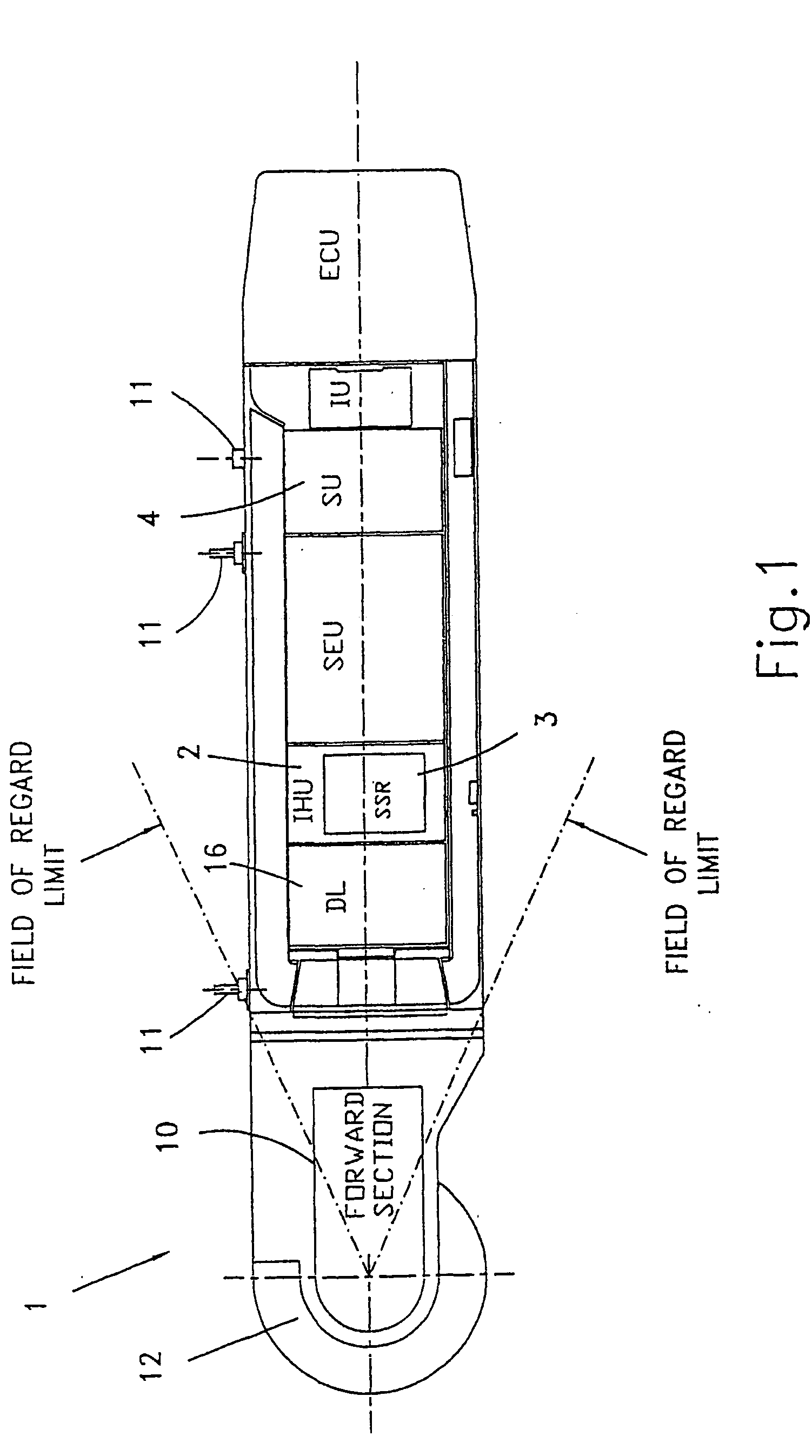
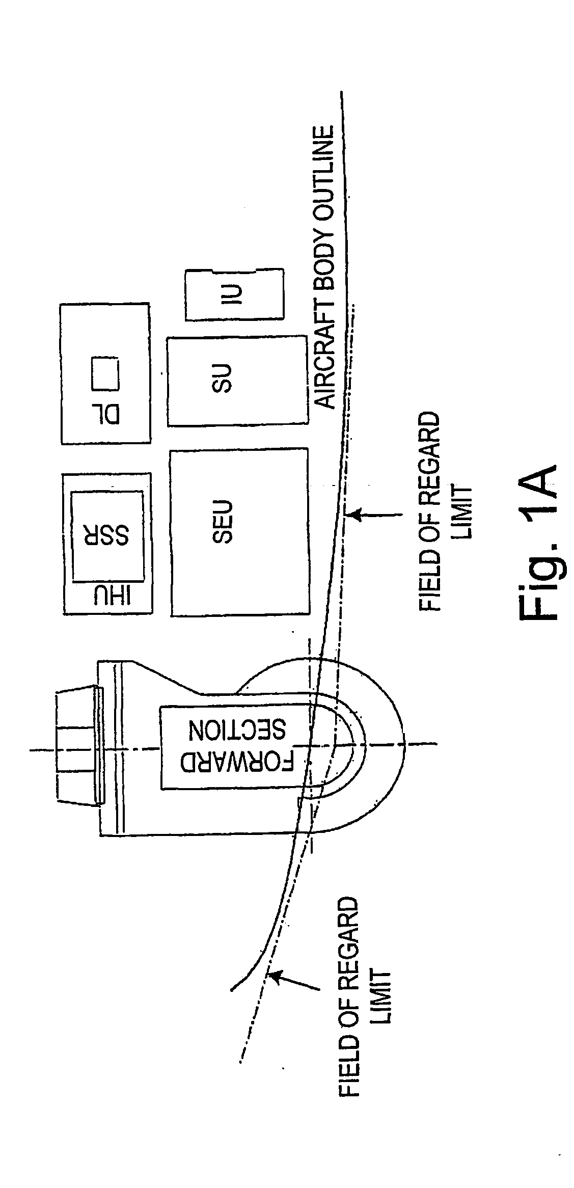
[0154] The invention was successfully implemented with the following parameters: [0155] Airborne pod configuration; [0156] Number of pixels: Visual array: 2000×2000, IR array 640×480; [0157] Integration times: 1-15 ms; [0158] Operational ranges: up to 30 km and altitude up to 10 km; [0159] Snapshot rate: 3 per second, both sensors arrays operating simultaneously. [0160] FOR: full spherical coverage, excluding a ±30 degrees backward looking cone; [0161] See also FIGS. 11 and 11A that are the result of an actual simulation of the scanning and overlapping process.

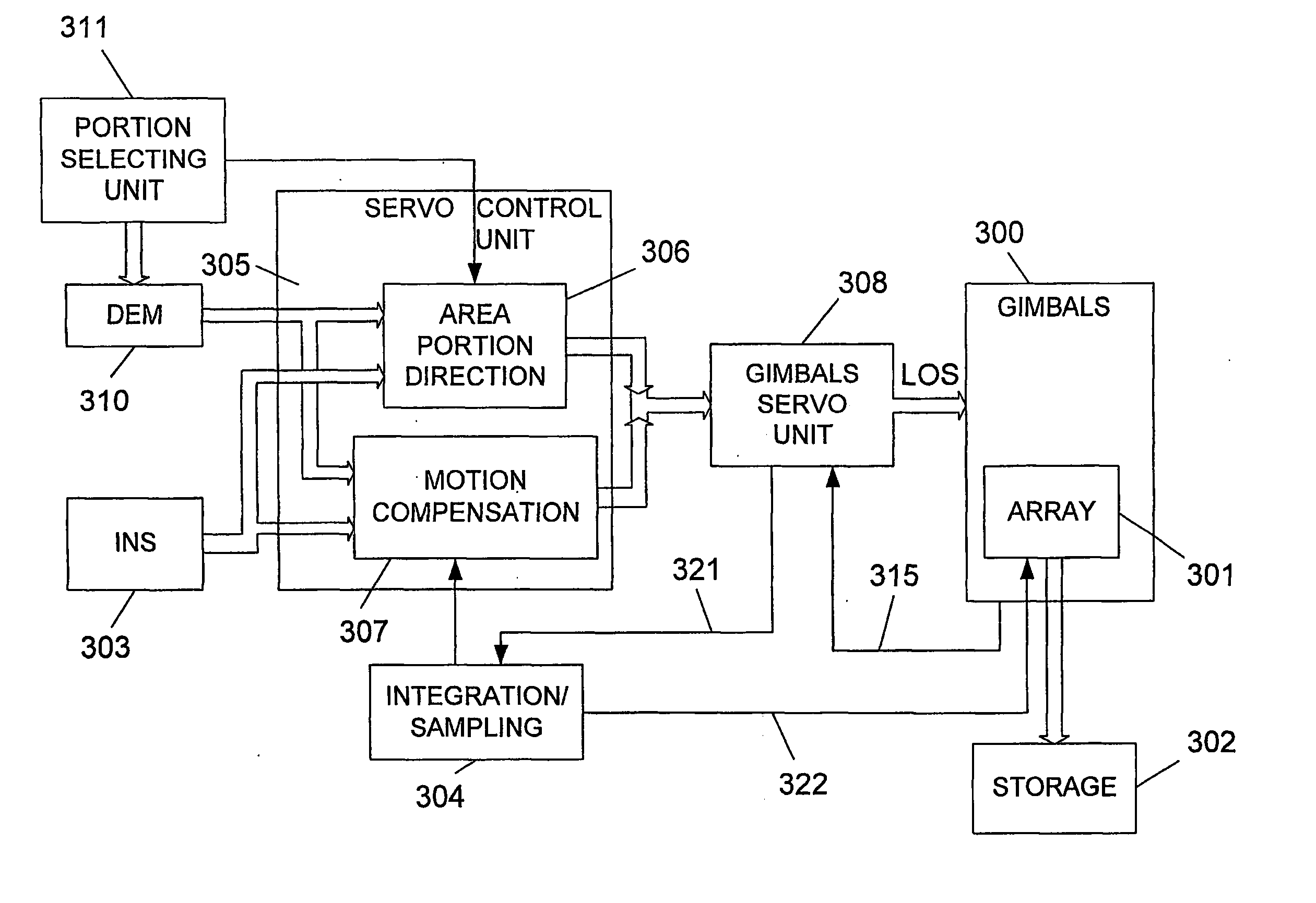
[0162] As said, in the embodiment of the invention as described above, the area scanning operation is performed by the gimbals that first direct the center of the array's LOS to the center of the relevant area portion, then, an exposure of the array to the light coming from the area portion occurs (i.e., the array starts integration of light from the area portion), and at the end of the exposure period the image of the area p...


PUM


Abstract

An airborne reconnaissance system comprising: (1) Gimbals having at least two degrees of freedom; (2) At least one array of light sensors positioned on the gimbals, for being directed by the same within at least two degrees of freedom; (3) Map storage means for storing at least one Digital Elevation Map of an area of interest, divided into portions; (4) Inertial Navigation System for real-time providing to a gimbals control unit navigation and orientation data of the aircraft with respect to a predefined global axes system;(5) Portion selection unit for selecting, one at a time, another area portion from the area of interest; and (6) servo means for directing the gimbals. The system uses data from the inertial navigation system and from the digital elevation map for real-time calculating direction to selected area portions, and for maintaining the direction during integration of light from the terrain, and for producing corresponding images of area portions.

Description

FIELD OF THE INVENTION [0001] The present invention relates to a system for carrying out airborne reconnaissance. More particularly, the present invention relates to an airborne reconnaissance system which comprises one or more arrays of light-sensitive sensors, such as UV, visible, IR, multi / hyper-spectral, or active illumination, the line of sight of which being directed by means of gimbals having at least two degrees of freedom, said system further uses an Inertial Navigation System (INS) for providing accurate tracking and capturing, and for providing 3D motion compensation. The sensors and INS are preferably mounted on the gimbals. BACKGROUND OF THE INVENTION [0002] Airborne reconnaissance systems have been widely used for many years now, particularly for obtaining images from the air of areas of interest. [0003] Originally, a film camera was used on board aircraft for capturing the images. The main problem of the airborne, film-camera based reconnaissance system is the length ...

Claims


Application Information

Patent Timeline
IPC IPC(8): F42B15/08B64D47/08F41G5/14F41G7/22G01C11/02G01C21/00G01C21/16G01S3/786
CPCF41G5/14F41G7/2213F41G7/2253G01S3/7864G01C11/025G01C21/005G01C21/165F41G7/2293G01C21/1656G01C11/02G01S3/786
Inventor GREENFELD, ISRAELYAVIN, ZVIUHL, BERND
Owner THE STATE OF ISRAEL MINIST OF AGRI & RURAL DEV AGRI RES ORG ARO VOLCANI CENT
Why Eureka
Try Eureka