Optical apparatuses using the near-field light

a technology of optical apparatus and nearfield light, which is applied in the direction of material analysis using wave/particle radiation, instruments, nuclear engineering, etc., can solve the problems of low level of efficiency, low generation efficiency of probes, and decrease in the s/n (signal-to-noise) ratio of detected signals, so as to achieve excellent s/n ratio and sacrifice spatial resolution

Inactive Publication Date: 2005-09-27
HITACHI LTD
View PDF57 Cites 51 Cited by
  • Summary
  • Abstract
  • Description
  • Claims
  • Application Information

AI Technical Summary

Benefits of technology

[0015]It is the object of the present invention to remove the background light presenting the above-discussed problem without sacrificing the ...

Problems solved by technology

However, generation efficiency of the probe is low.
This low level of efficiency becomes a problem when the near-field light technologies are applied to various fields.
The above-mentioned conventional methods (1) through (5) each realize generation of the intense near-field light, but contain a problem in that light passes through a part other than the metallic surface and acts as background light, which brings on a decrease in the S/N (signal-to-noise) ratio of the detected signal.
Also, in the case where secondary light from the sample, such as fluorescent light and Raman light, is observed as signal light, the same problem is involved because secondary light generated by the above-mentioned background light becomes a background signal.
However, when dielectric materials are used as shading materials, it is difficult to achieve a sufficient shading property, and further problems, such as generation of heat, may occur.
When a metal with a high shading effect is used to avoid these problems, the following problem occurs.
Therefore, the aperture cannot be made sufficiently sm...

Method used


Image

  • Optical apparatuses using the near-field light
  • Optical apparatuses using the near-field light
  • Optical apparatuses using the near-field light

Examples


Embodiment Construction

[0040]Hereafter, various embodiments will be described with reference to the drawings.

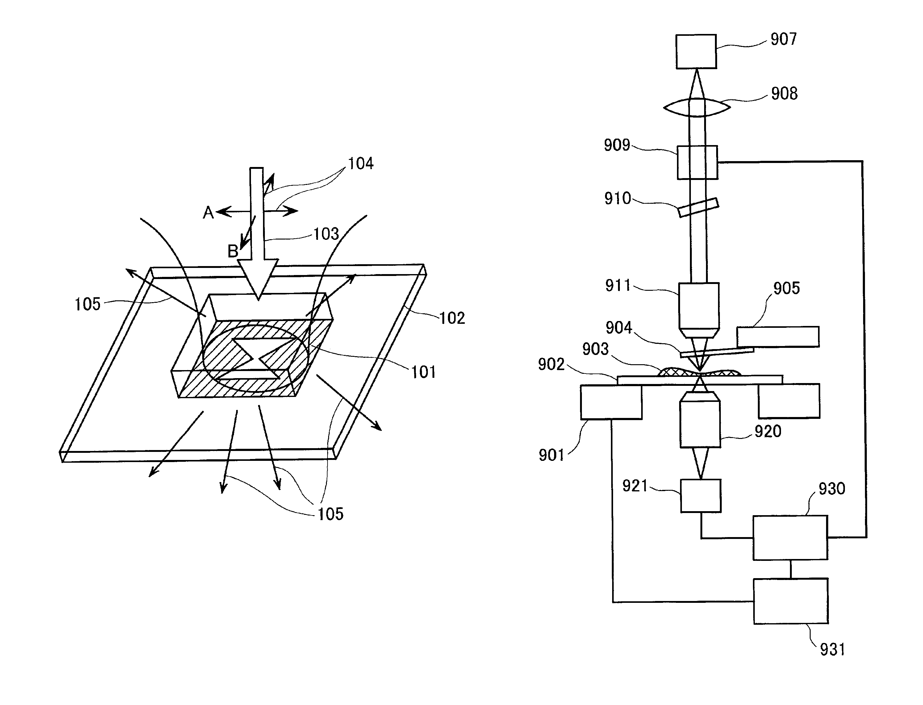
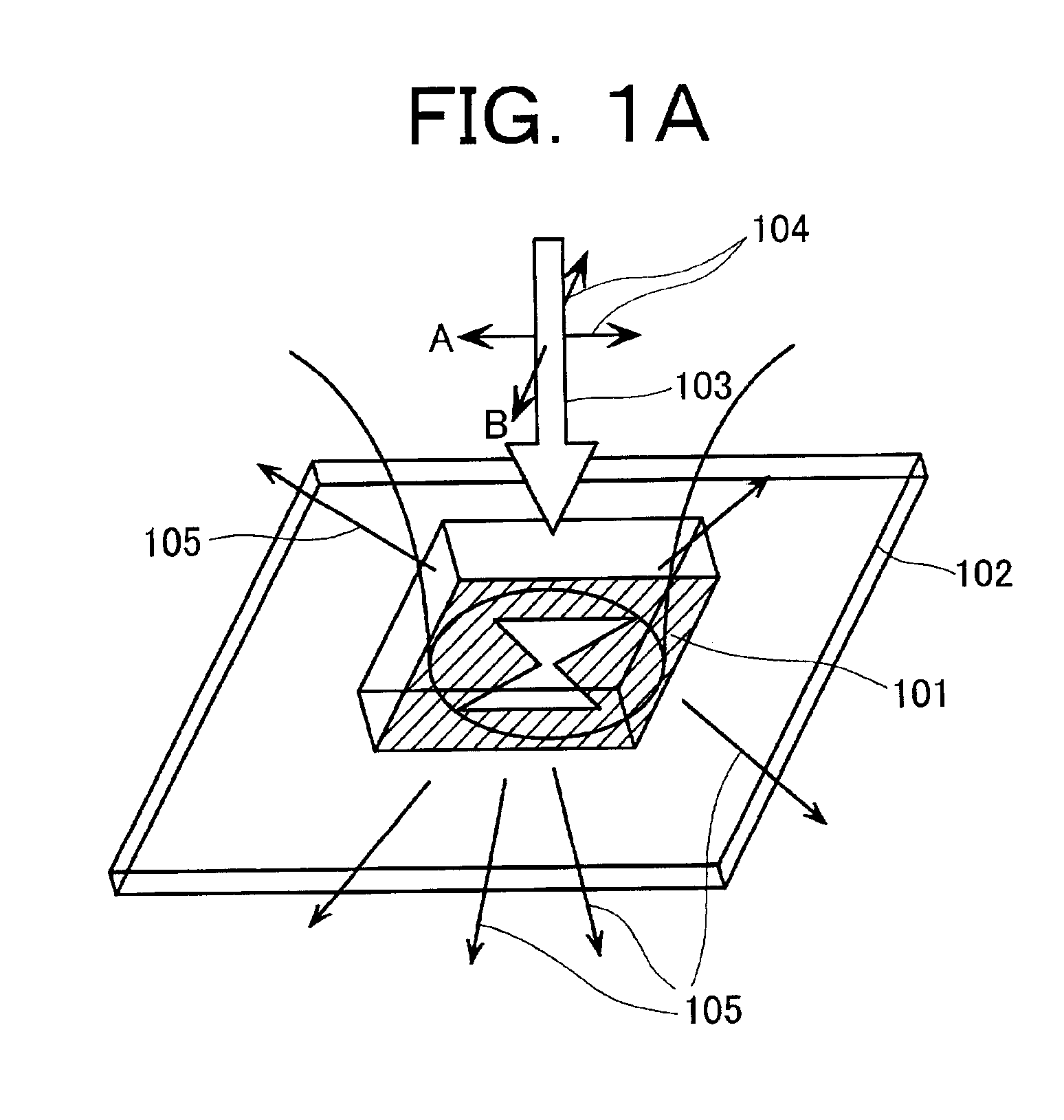
[0041]The near-field light probes used in accordance with the present invention are roughly divided into those in a planar shape and those in the shape of a pyramid or a cone. When the sample has excellent planarity, such as a medium for optical recording and a semiconductor wafer, it is appropriate and effective to use a planer probe. In an optical recording / reproduction device, a planar head is used as well as a planar probe. In the case, as in the multi-purpose microscopic apparatuses, where inaccessibility of the near-field light to the sample due to unevenness of the sample presents a problem, the probe is formed into a subulate shape (for example, the shape of a multiangular pyramid shape or the shape of a cone) and scanning is conducted with the tip thereof tracing along a shape of the sample.

[0042]First, the planar probe and optical recording / reproduction device that uses it will be describ...


PUM


Abstract

Optical apparatuses are provided that use near-field light, where high spatial resolution and high sensitivity are made compatible. Highly intense near-field light is generated in a narrow area using localized plasmons that are produced in a metal pattern 106 in a shape that bears anisotropy and is made to irradiate a measured subject. The direction of polarization 104 of incident light 103 is modulated and signal light is subjected to synchronous detection, so that background light is removed and high sensitivity is achieved.

Description

BACKGROUND OF THE INVENTION[0001]The present invention relates to optical apparatuses that use the near-field light, such as optical microscopes, optical measurement instruments, spectroscopic instruments, and optical recording / reproduction apparatuses.[0002]In the conventional optical microscope, light is focused with lenses. In this case, the spatial resolution is limited by the light wavelength.[0003]On the other hand, the near-field optical microscope uses a probe having a microstructure whose dimensions are of an order of nanometer, for example, a micro aperture whose diameter is of an order of nanometer. When the microstructure is irradiated with light, localized light called near-field light is generated in the vicinity thereof. If the microstructure is brought close to a sample and the object (the sample) is illuminated with the near-field light, the localized near-field light is converted to propagating light, depending on the complex refractive index of the sample, that ca...

Claims


Application Information

Patent Timeline
IPC IPC(8): G12B21/06G12B21/00G01Q10/00G01Q60/18G01Q60/22G01Q70/06G01Q80/00G11B7/135
CPCB82Y20/00B82Y35/00G01Q60/22
Inventor KIGUCHI, MASASHIMATSUMOTO, TAKUYAHASHIZUME, TOMOHIROORITA, ISAMU
Owner HITACHI LTD
Why Eureka
Try Eureka