Method and apparatus for monitoring telephone status

a telephone status and telephone technology, applied in the field of methods and apparatus for monitoring telephone status, can solve the problems of requiring significant user time and a costly manner

Inactive Publication Date: 2006-03-07
QUALCOMM INC
View PDF25 Cites 29 Cited by
  • Summary
  • Abstract
  • Description
  • Claims
  • Application Information

AI Technical Summary

Problems solved by technology

Conventional telephone systems can provide a caller's status information, but do so in a costly manner that requires significant user time.

Method used


Image

  • Method and apparatus for monitoring telephone status
  • Method and apparatus for monitoring telephone status
  • Method and apparatus for monitoring telephone status

Examples


Embodiment Construction

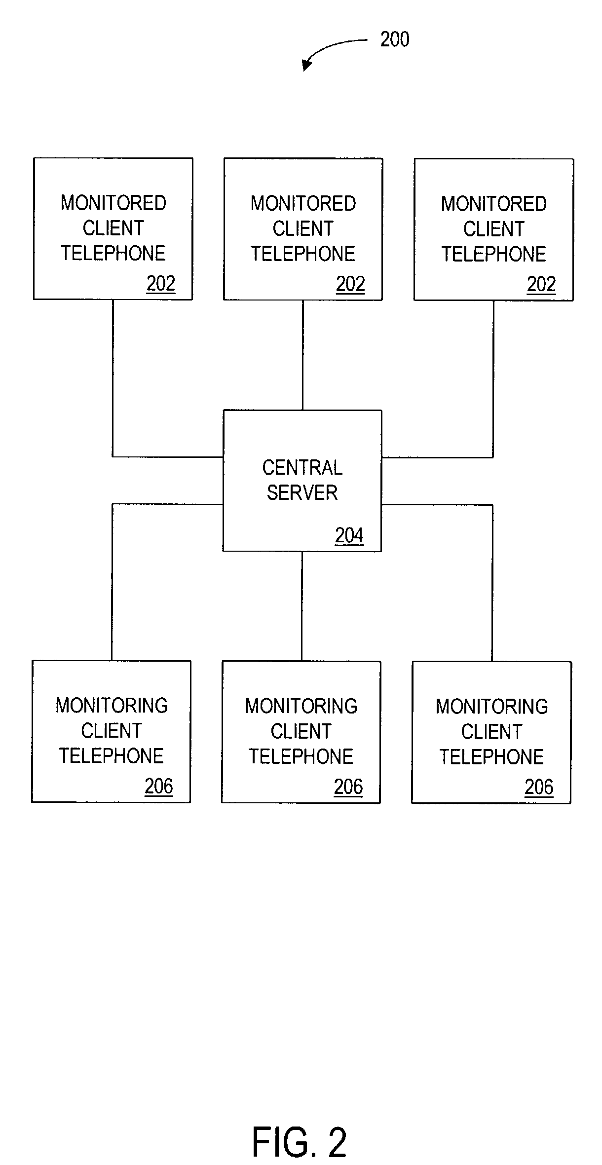
[0020]The telephone disclosed in various embodiments of the present invention may be configured in accordance with a “plug-and-play” protocol. The user of the telephone simply plugs the telephone into a telephone jack. The telephone automatically connects to the central server, receives TCP / IP information from the server for future communications and registers the client. The client then selects the parties that the client wishes to monitor.

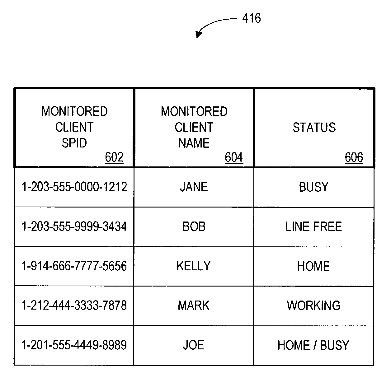
[0021]The client may select parties to monitor by programming the parties' telephone numbers into the client's local telephone or by a directory lookup by name. The client's telephone communicates these telephone numbers to the central server and the central server verifies that the parties agree to be monitored. Once the parties agree, the parties register with the system. The client may also select parties to monitor by contacting the service associated with the central server off-line and submitting a request to monitor the specified parties. ...


PUM


Abstract

The monitor is for monitoring the status of a first client telephone, and for sending this status information via a central server to an authorized second client telephone. The central server stores a database of registered client telephones and corresponding client telephones that the client may monitor. A user of a registered client telephone monitors in real time the telephone status of registered friends, family, or co-workers that have agreed to be monitored by the user.

Description

[0001]The present application is a continuation-in-part of U.S. patent application Ser. No. 09 / 282,360 filed Mar. 31, 1999, now abandoned.BACKGROUND OF THE INVENTION[0002]Conventional telephone systems can provide a caller's status information, but do so in a costly manner that requires significant user time. For example, the office based PBX telephone system provides a caller with status information.[0003]Determining whether the party's line is busy or available requires a caller's telephone to poll a central station and wait for a call back to receive status information.[0004]At present, the telephone industry is in the process of switching to digital technology (i.e., Integrated Services Digital Network (ISDN), and Asymmetric Digital Loop (ASDL)). ISDN is an international communications standard for sending voice and data over telephone lines. ISDN technology transmits data at a rate far faster than prior telephone connection technologies. ISDN lines generally include three chann...

Claims


Application Information

Patent Timeline
Patent Type & Authority Patents(United States)
IPC IPC(8): H04M3/42H04M1/2757H04M3/22H04M3/38H04M7/00H04M11/00H04Q3/58
CPCH04M1/2535H04M3/4228H04M3/42314H04M3/42374H04M1/274516H04M2207/08H04M3/2272H04M3/38H04M3/42093H04M3/42323H04M3/42365H04M3/4931H04M7/0009H04M7/006H04M2203/6009H04M2203/609H04M7/128H04M7/1295H04M1/2757
Inventor JORASCH, JAMES A.WALKER, JAY S.FINCHAM, MAGDALENA M.DICKERSON, JOHN B.KESSMAN, MARC D.GELMAN, GEOFFREY M.TULLEY, STEPHEN C.ALDERUCCI, DEAN P.
Owner QUALCOMM INC
Why Eureka
Try Eureka