
Method and device for prediction of a zero-crossing alternating current

a technology of alternating current and zero-crossing, which is applied in the direction of automatic controllers, high-tension/heavy-dress switches, electric variable regulation, etc., can solve the problems of increasing the risk of greater damage to said equipment, the number of alternating currents before, and the amount of material burned away is too large, so as to achieve good exactness

Inactive Publication Date: 2006-03-07
ABB GROUP SERVICES CENT
View PDF12 Cites 12 Cited by
  • Summary
  • Abstract
  • Description
  • Claims
  • Application Information

AI Technical Summary

Benefits of technology

[0007]The object of the present invention is to provide an apparatus and a method of the type defined in the introduction, which make it possible to predict an early zero-crossing of an alternating current with a good exactness after occurrence of a fault current in a current path.
[0009]The apparatus according to the invention designed in that way enables a reliable prediction of a future zero-crossing, since a future zero-crossing is calculated on the basis of said current values detected while considering both the dc-level of the alternating current and how rapidly it falls. It gets by this possible to control a breaker so that the mechanical movement of a contact member is started a certain period of time before a future zero-crossing for obtaining breaking exactly at the zero-crossing, would there be a desire thereof. There is neither any risk of making any attempt to break before any zero-crossing has occurred, since this is first predicted.
[0011]According to a preferred embodiment of the invention said current detecting members are adapted to detect the time for a zero-crossing of the current, and the arrangement is adapted to consider the time for a detected zero-crossing when predicting a time for a future zero-crossing of the alternating current. By firstly detecting a zero-crossing in this way and starting from this time when calculating a future zero-crossing the prediction of a future zero-crossing will be reliable.
[0015]According to another preferred embodiment of the invention the current detecting members are adapted to deliver the value of the alternating current of two consecutive current peaks to said arrangement, and the arrangement is adapted to form an average of these two current values for use as said dc-level when calculating said future zero-crossing of the alternating current. The dc-level may in this way easily be determined with the accuracy aimed at.
[0016]According to another preferred embodiment of the invention the apparatus is designed for an alternating current in the form of a three-phase alternating current, the arrangement is adapted to calculate the dc-level for two phases by determining an average of two consecutive current peaks of the respective phase, and the arrangement is adapted to calculate the decay with time of the dc-level on the basis of the relation between these two dc-levels and then use it when predicting a future zero-crossing. The dc-decay may in this way at three-phase faults be very rapidly calculated and a condition for an early prediction of a future zero-crossing of the alternating current is by that fulfilled.
[0017]According to another preferred embodiment of the invention the apparatus comprises also members adapted to calculate the ac-decay of the alternating current, i.e. the reduction of the amplitude of the alternating current with the time, on the basis of current values delivered by said current detecting members, which further improves the accuracy of the prediction, but it may require a longer time for calculation of the time for a future zero-crossing.

Problems solved by technology

However, the alternating current receives upon occurrence of said fault usually a direct current component (dc-component), the magnitude of which depends upon the time for occurrence of the fault, and this dc-component is superposed on the alternating current, which in the worst case may result in a duration of several periods of the alternating current before any zero-crossing occurs.
This long waiting means of course an imminent risk of greater damage on said equipment than would the breaking have taken place at an earlier time.
It is for that sake not sure that it is always desired to break the current when the first zero-crossing occurs, since the dc-component may still be that great that the energy of an arc generated on a contact location would be to high and the amount of material burned away would be to large, so that the breaker or switching device may be partially destroyed or fail.

Method used


Image

  • Method and device for prediction of a zero-crossing alternating current
  • Method and device for prediction of a zero-crossing alternating current
  • Method and device for prediction of a zero-crossing alternating current

Examples


Embodiment Construction

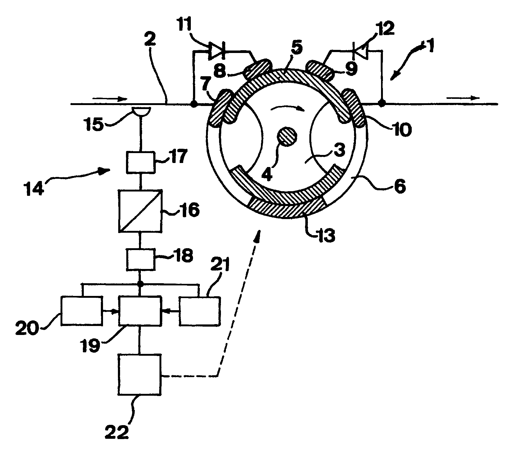
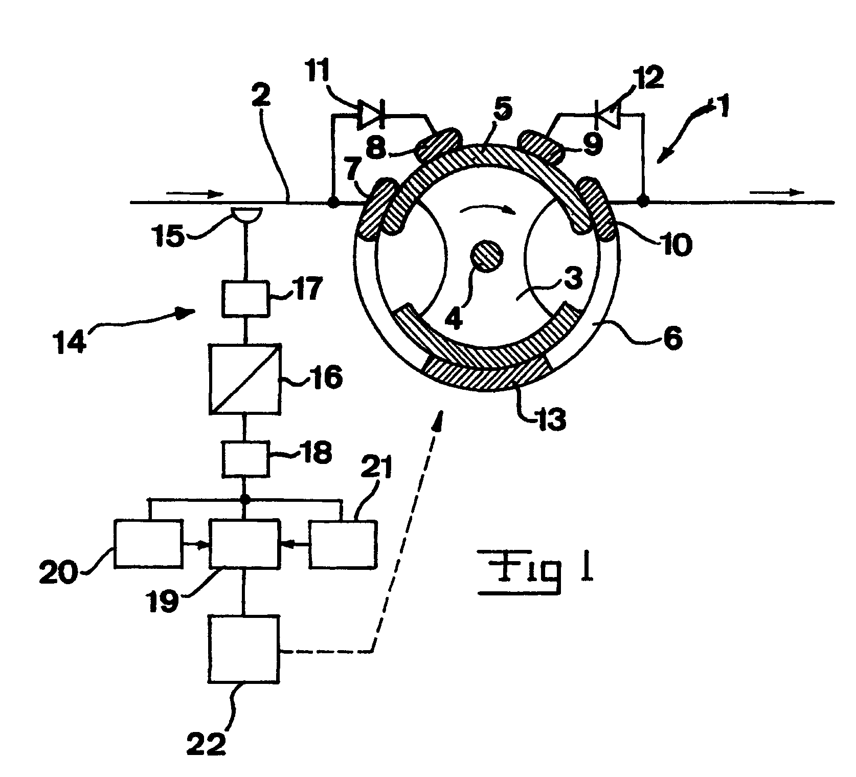
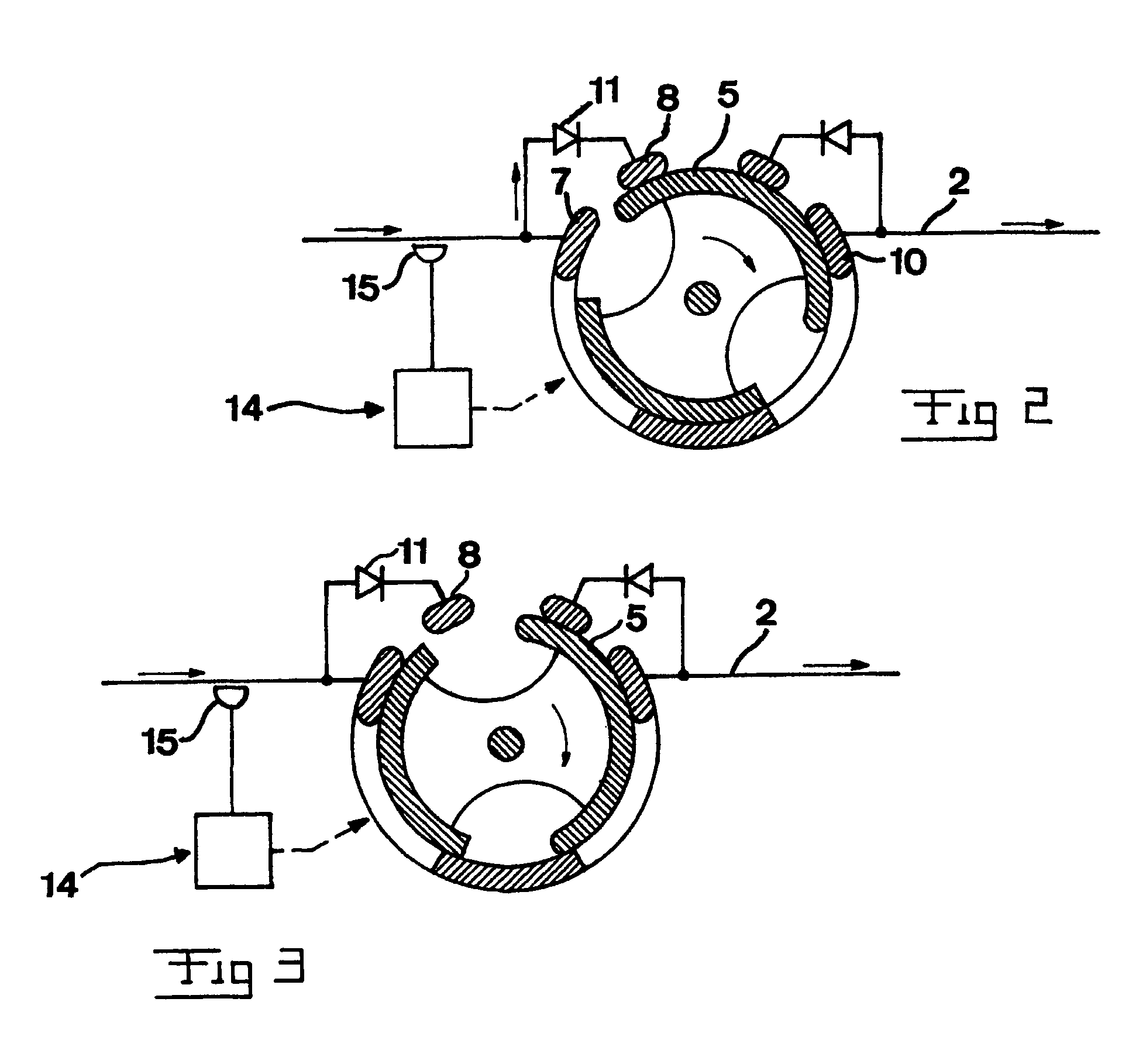
[0034]An electric switching device for alternating current of the type to which the invention is particularly well applicable is schematically illustrated in FIG. 1, namely a such that is described in the Swedish patent application 9904164-2 mentioned before, and which here is provided with an apparatus for predicting a zero-crossing of an alternating current according to a preferred embodiment of the invention. The electric switching device 1 is connected in a current path 2 so as to be able to rapidly open or close this and by that break and establish, respectively, the current in the current path. One such switching device is arranged per phase, so that a three phase network has three such switching devices on one and the same location. The switching device has an inner cylinder 3, which may be rotated around an axle 4 and has a movable contact part 5. A second cylinder 6 is arranged externally of the cylinder 3 and has four contacts 7–10 arranged along the movement path of the m...


PUM


Abstract

An apparatus (14) for detecting a zero-crossing of an alternating current after occurrence of a fault in a current path (2) for determining a suitable time for opening an electric switching device (2) arranged in the current path for breaking the current in the current path comprises members (15) adapted to detect the current in the current path. An arrangement (19) is adapted to calculate the dc-level of the current and the decay of the dc-level with time on the basis of values of the alternating current detected and also predict the time for a future zero-crossing of the alternating current on the basis of at least current values obtained through said current detection, the dc-level calculated, the dc-decay calculated and information about the period time of the alternating current.

Description

FIELD OF THE INVENTION AND PRIOR ART[0001]The present invention relates to an apparatus for predicting a zero-crossing of an alternating current after occurrence of a fault current in a current path for determining the suitable time for opening an electric switching device arranged in the current path for breaking the current in the current path as well as a method for such a prediction.[0002]“Electric switching device” is to be given a broad sense and covers not only such ones having a mechanical movement between different parts for obtaining an opening through physical separation of two parts in the current path, but also semiconductor devices, such as IGBTs or the like, which open by going to blocking state and by that breaking the current therethrough. “Electric switching device” also comprises so called transfer switches through which then a current in a current path may be broken upon occurrence of a fault current in the current path for switching in another current path inste...

Claims


Application Information

Patent Timeline
Patent Type & Authority Patents(United States)
IPC IPC(8): G06F19/00G05F1/10H01H33/59H01H9/56H01H33/00
CPCH01H33/006H01H9/56
Inventor LARSSON, PERBACKMAN, MAGNUSJONSSON, LARS
Owner ABB GROUP SERVICES CENT
Learn More