Conveying mechanism

a technology of conveying mechanism and transfer belt, which is applied in the direction of conveyor parts, thin material processing, article feeders, etc., can solve the problems of not always avoiding the meandering of the transfer belt within the image forming area, the position deviation, and the position deviation, so as to reduce the number of components

Inactive Publication Date: 2006-03-14
BROTHER KOGYO KK
View PDF33 Cites 12 Cited by
  • Summary
  • Abstract
  • Description
  • Claims
  • Application Information

AI Technical Summary

Benefits of technology

[0012]An object of the present invention is to overcome the above described shortcomings of the prior art and to provide a conveying mechanism capable of preferably avoiding the meandering of the portion of a transfer belt located in an image forming area.

Problems solved by technology

If the transfer belt is positionally deviated in this manner, such problems occur that the recording medium transferred by the transfer belt is positionally deviated, and that the image forming position on the recording medium is also positionally deviated.
However, the configurations as described in the above patent documents are aimed at inhibiting the meandering of the transfer belt only in the engaging area between the transfer rollers and the transfer belt, so that meandering of the transfer belt within the image forming area is not always preferably avoided.
However, in the portion of the transfer belt located in the image forming area, the transfer belt often continues to cause the positional deviation by meandering.

Method used


Image

  • Conveying mechanism
  • Conveying mechanism
  • Conveying mechanism

Examples


first embodiment

(First Embodiment)

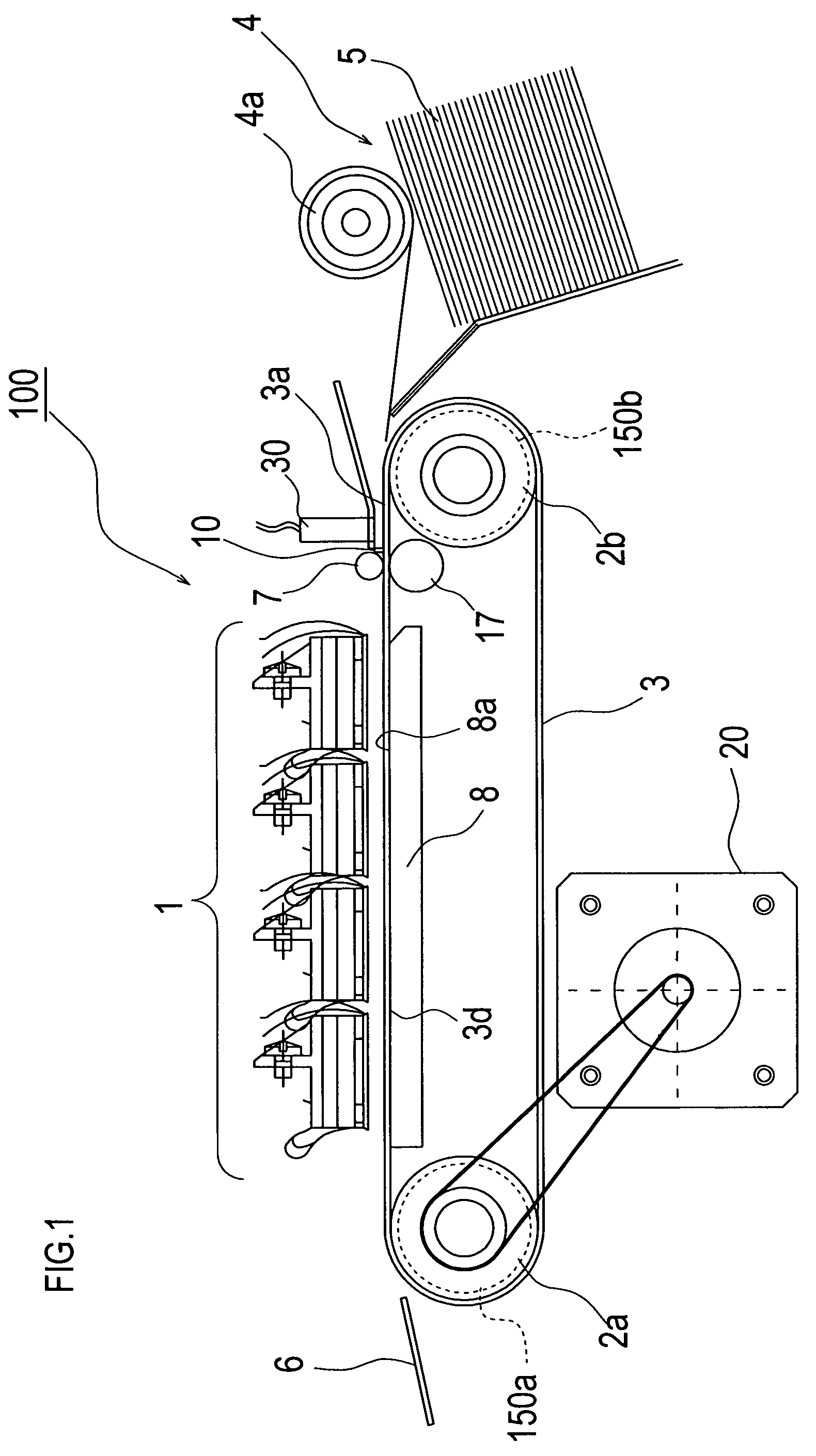
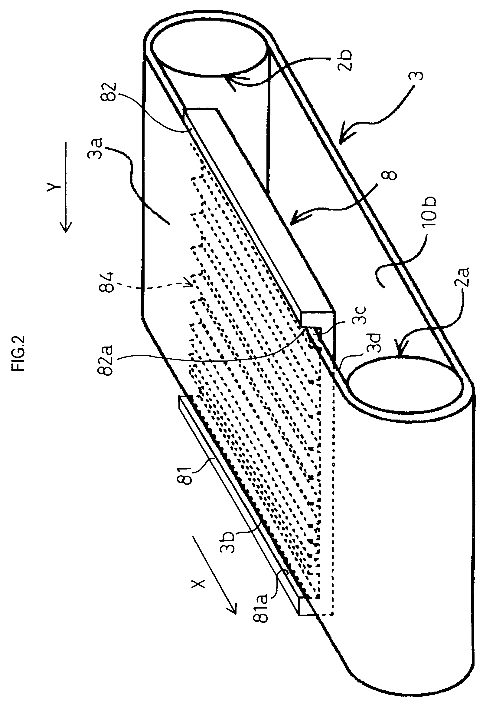
[0076]FIG. 1 is a schematic side view showing the main part of an ink jet printer provided with a conveying mechanism 100 of the present embodiment. FIG. 2 is a schematic perspective view showing the relationship among a transfer belt 3, transfer rollers 2a and 2b, and a guide member 8 in the conveying mechanism 100.

[0077]As illustrated in FIG. 1, this printer comprises a print head 1 of an inkjet system, two transfer rollers 2a and 2b, a cylindrical (endless) transfer belt 3 wound around these transfer rollers 2a and 2b, and a guide member 8.

[0078]In this printer, a recording medium 5, such as paper and cloth, is fed toward the transfer belt 3 from a supply unit 4 by the drive of a pickup roller 4a. Then the transfer belt 3 transfers the recording medium 5 to an image forming area under the print head 1 by the rotation of the transfer rollers 2a and 2b. Subsequently, an image is formed and recorded on the recording medium 5 by the discharge of ink from the print h...

second embodiment

(The Second Embodiment)

[0104]In the conveying mechanism of the present embodiment, only the configurations of the transfer belt and the guide member differ from those of the aforementioned first embodiment. Therefore, only the different configurations will be mainly described, while the components with the same configurations are denoted with the same reference numerals and the description of the same is omitted.

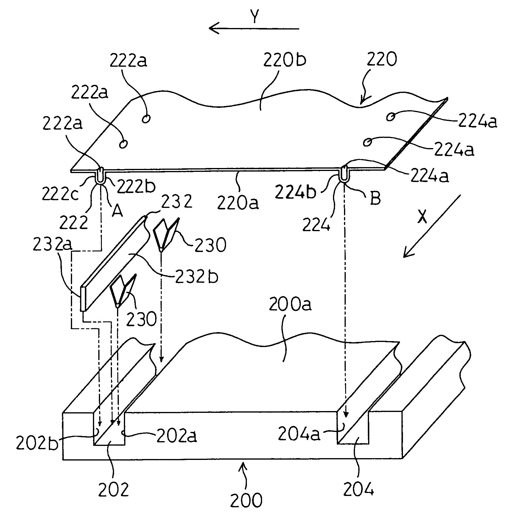
[0105]FIG. 3 is an explanatory view showing the relationship between a guide member 200 and a transfer belt 220 in the conveying mechanism of the present embodiment.

[0106]The guide member 200 of the present embodiment is provided at a position facing the print head 1 (image forming area) via the transfer belt 220 like the guide member 8 of the first embodiment.

[0107]The guide member 200 of the present embodiment is disposed so as to slightly push up the transfer belt 220 from the under surface of the transfer belt 220, thereby applying tension to the transfer belt 220.

[0108]...

third embodiment

(The Third Embodiment)

[0163]In the conveying mechanism of the present embodiment, only the configurations of the transfer belt and the guide member mainly differ from those of the aforementioned first embodiment. Therefore, only the different configurations will be mainly described, while the components with the same configurations are denoted with the same reference numerals and a description of the same is omitted.

[0164]FIG. 7 is an explanatory view showing the relationship between a guide member 300 and a transfer belt 320 in the conveying mechanism of the present embodiment.

[0165]The guide member 300 of the present embodiment is provided at a position facing the print head 1 (image forming area) via the transfer belt 320, like the guide member 8 of the first embodiment. The guide member 300 is a plate-like member with a configuration such as a rectangular parallelepiped.

[0166]A transfer belt 320 has a ring configuration (endless configuration). Ring-shaped endless guide portions...


PUM


Abstract

A conveying mechanism capable of preferably inhibiting the portion of a transfer belt located in an image forming area from meandering. A plurality of ribs (84) are provided so as to extend approximately parallel to a transfer direction (X) on an upper surface (8a) of a guide member (8). The intervals between the ribs (84) are constituted to be gradually narrowed in the left direction (Y). A transfer belt (3) is gradually moved in the left direction (Y) by the abutment between an inner side face (3d) thereof and the plurality of ribs (84). The movement of the transfer belt (3) in the left direction (Y) is limited and restricted by the abutment between a right side face (81a) of a projection piece (81) of the guide member (8) and a left side face (3b) of the transfer belt (3).

Description

TECHNICAL FIELD[0001]The present invention relates to a conveying mechanism and more specifically, to a conveying mechanism which inhibits positional deviation of a transfer belt in its width direction when the transfer belt wound around transfer rollers is transferred.BACKGROUND ART[0002]Image forming apparatuses, for recording images on recording mediums such as paper or the like, for example, inkjet printers with inkjet heads (corresponding to recording heads), have been conventionally known. In the inkjet printer, the image is formed (printed) on the recording medium, e.g. paper or the like, which is placed on a transfer belt wound around at least two transfer rollers, in an image forming area. The transfer rollers are driven by a driving roller, and the transfer belt is moved cyclically by the transfer rollers. Subsequently, the recording medium, e.g. paper or the like, which is placed on the transfer belt, is transferred to the image forming area facing the inkjet head, and th...

Claims


Application Information

Patent Timeline
Patent Type & Authority Patents(United States)
IPC IPC(8): B65G15/60B65G15/64
CPCB65G15/64
Inventor NAKASHIMA, ATSUHISA
Owner BROTHER KOGYO KK
Why Eureka
Try Eureka