Method for manufacturing fiber-reinforced plastic products

a technology of reinforced plastics and fibers, which is applied in the field of fiber-reinforced plastic products, can solve the problems of extending the flow time of resin inside the fiber preform, affecting the quality of fiber reinforced plastic products, so as to avoid dry glass fibers and/or white spots, and the effect of greater thickness

Active Publication Date: 2018-03-15
COVESTRO DEUTSCHLAND AG
View PDF6 Cites 5 Cited by
  • Summary
  • Abstract
  • Description
  • Claims
  • Application Information

AI Technical Summary

Benefits of technology

[0015]The purpose of the present invention is to provide a method for manufacturing fiber-reinforced plastic products, which can not only realize the complete and sufficient impregnation of fiber preforms that have greater thicknesses or can hardly be completely impregnated by the resin, while avoiding dry glass fibers and / or white spots and other defects, but also is conducive to the implementation during the manufacturing process.

Problems solved by technology

The increase of the product size, particularly the increase of the thickness, will make it much more difficult to discharge the air from the sealing system, and extend the flow time of the resin inside the fiber preform.
Restrained by the viscosity and gel time of the resin, vacuum infusion of products with greater thicknesses becomes more difficult.
The semi-permeable membrane disposed above the fiber preform can continuously discharge the air within the fiber preform to avoid that a part of the air was surrounded by resin due to the uneven flow of the resin, and thus results in white spots or dry glass fibers and other defects.
However, this method also has the following restrictions: since the resin needs to impregnate the entire fiber preform from bottom to top, the resin needs to flow through the entire thickness of the fiber preform.
Limited by resin viscosity and gel time, when the resin cannot completely impregnate the entire thickness of the fiber preform within its gel time, the application of this method will be restricted.
Thus, it will be much more difficult to make the resin flow between the carbon fibers and impregnate the resin.
Therefore, the carbon fiber preform is generally harder to be infused than the glass fiber preform.
A significant drawback of this method is: from the beginning of the infusion, the resin flows to the middle of the fiber preform from both the top and the bottom simultaneously.
During the entire process of infusion, the air in the most middle part of the fiber preform can hardly be discharged effectively.
Such results are: the middle part of the fiber preform is not sufficiently impregnated, and thus forms white spots or dry glass fibers.
This method avoids the problem that the fibers in the middle of the fiber preform cannot be sufficiently impregnated caused by the injection of the resin from both the top and the bottom of the fiber preform simultaneously, but also brings some new technical problems: first, the injection port and the suction port arranged above the fiber preform will tightly press against the fiber preform under the action of atmospheric pressure to form imprints, making the fibers bend and affecting the mechanical properties and the surface quality of the products; second, in said method, both of the injection port and the suction port above the fiber preform are connected with the flow mesh above the fiber preform to strengthen the speeding of discharging the air within the fiber preform at the beginning stage of resin injection.
Practices prove that by using said method, the resin injected though the injection port above the fiber preform will flow into the suction port through the flow mesh very quickly, resulting in the interruption of the vacuum pumping.
At the moment, the air within the fiber preform can no longer be discharged, producing dry glass fibers or white spots or other defects below the flow mesh.
A significant drawback of this method is: the injection tube placed above the fiber preform needs to suspend above the fiber preform to avoid the formation of imprints caused by the direct contact of injection tube and injection port with the fiber preform, and ultimately affecting the mechanical properties and surface quality of the products.
Practices prove that it is very difficult to carry out said method during the manufacturing process, and thus it can hardly be used in practical production.
Because of the irregularity of the flow of the resin, said discharge passage can easily be blocked by the resin penetrating from the bottom of the fiber preform, causing the air near said passage impossible to be discharged continuously.
Meanwhile, since the position of said discharge passage is farthest away from the injection port of the resin, i.e., the last part to be impregnated in the entire fiber preform, the result of the discharge passage being blocked by the resin is that the glass fibers near the position of said discharge passage can easily form dry glass fibers or white spots because the air cannot be sufficiently discharged.

Method used


Image

  • Method for manufacturing fiber-reinforced plastic products
  • Method for manufacturing fiber-reinforced plastic products
  • Method for manufacturing fiber-reinforced plastic products

Examples


first example

The First Example

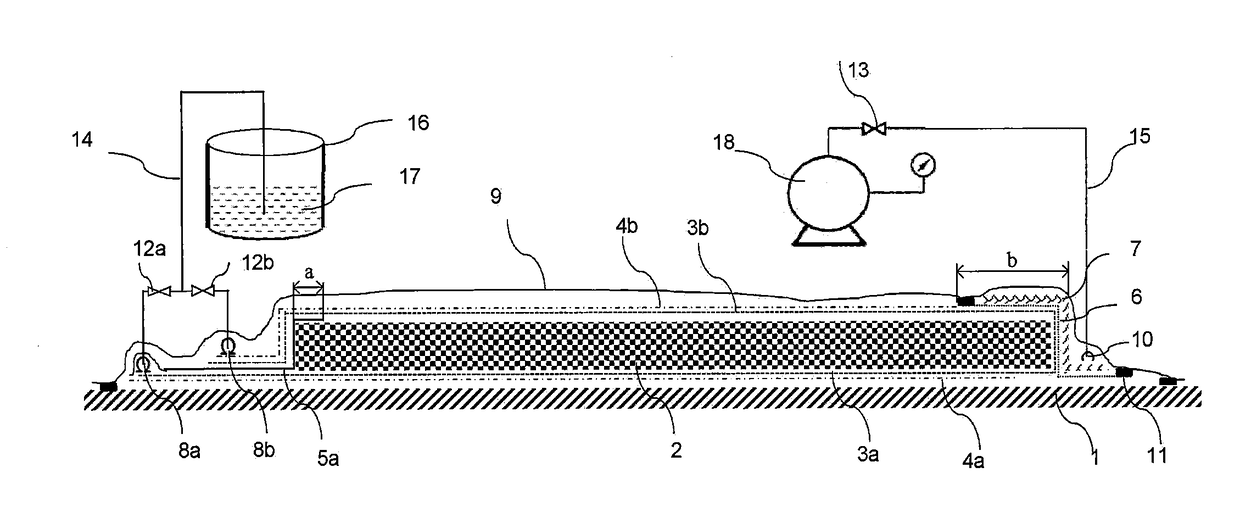
[0067]Please refer to FIG. 1. Said figure shows the First Example according to the method for manufacturing fiber-reinforced plastic products of the present invention.

[0068]The method for manufacturing fiber-reinforced plastic products disclosed in the present invention is especially suitable for fiber preforms having relatively large thicknesses or that can hardly be impregnated by the resin, wherein, the so-called “fiber preforms having relatively large thicknesses” generally refers to the fiber preforms that can hardly have their entire thicknesses, which are determined by the property of the resin used therein, fully impregnated within the gel time of the resin. In the present invention, the resin can be selected from common resins such as polyurethane resin, epoxy resin, etc., as well as any uncommon resin that is suitable for impregnation of fiber preforms.

[0069]The following briefly introduces the steps of applying the method for manufacturing fiber-reinforce...

second example

The Second Example

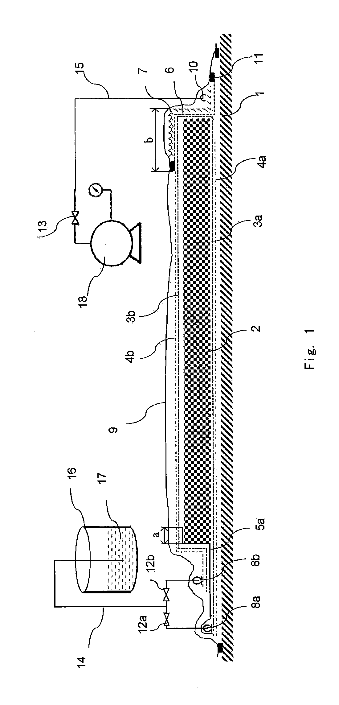
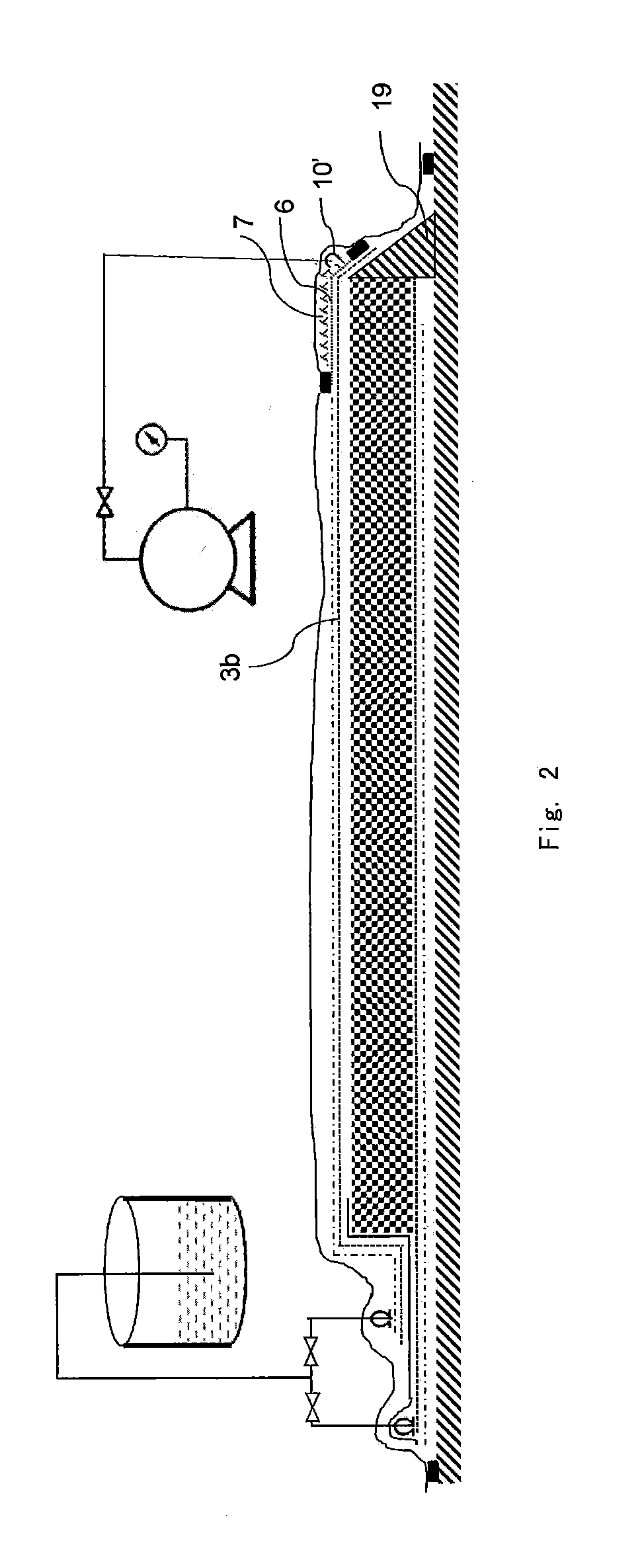
[0077]Please refer to FIG. 2. Said figure shows the Second Example according to the method for manufacturing fiber-reinforced plastic products of the present invention.

[0078]As shown in FIG. 2, a stopper 19 was arranged on the air-pumping side of the fiber preform 2 or a mold 1 to replace the breathable felt 7 in the First Example. In FIG. 2, the stopper is in a triangle shape, but in the actual use, stoppers with other suitable shapes can also be selected.

[0079]The arrangements of the parts in the Second Example are identical to those of the First Example, except that the second peel ply 3b, the semi-permeable membrane 6 and the breathable felt 7 were disposed on the stopper 19, and a suction port 10′ was also arranged on the stopper 19.

[0080]Since in the Second Example, the stopper 19 was used in place of the second peel ply 3b, the semi-permeable membrane 6 and the breathable felt 7 that were disposed at the edge of the fiber preform 2, the required lengths of t...

third example

The Third Example

[0082]Please refer to FIG. 3. Said figure shows the Third Example according to the method for manufacturing fiber-reinforced plastic products of the present invention.

[0083]On the basis of step (c) of the Second Example, the second peel ply 3b, when disposed, may further extend to above the stopper 19 and the mold 1 so as to form a peel ply extension segment 3c as shown in FIG. 3 (shown as a dashed line in FIG. 3).

[0084](d1) A suction port 10″ was arranged over the peel ply extension segment 3c. A second film 5b was used to partly or completely cover the peel ply extension segment 3c and the suction port 10″, and to partly cover the fiber preform 2. The covered width of the fiber preform may be 10% to 70%, preferably 20% to 50%, of the width of the area without a flow mesh.

[0085](d2) A third peel ply 3d (shown as a dashed line in FIG. 3) was disposed on the second film 5b. As shown in FIG. 3, one side (i.e. the left side of FIG. 3) of the third peel ply 3d over the ...


PUM

PropertyMeasurementUnit
vacuum pressureaaaaaaaaaa
widthaaaaaaaaaa
widthaaaaaaaaaa

Abstract

The present application relates to a method for manufacturing fiber-reinforced plastic products. This method comprises: preparing a fiber preform on a mold; disposing first and second flow meshes and first and second demolding cloths; sealing the fiber preform to form a vacuum system by pumping; penetrating the resin through the first peel ply via the first flow mesh and impregnates the fiber preform from bottom to top; penetrating the resin through the second peel ply via the second flow mesh and impregnates the fiber preform from top to bottom; and attaining a resin-impregnated fiber perform and finally attaining fiber-reinforced plastic products.

Description

FIELD OF INVENTION[0001]The present invention relates to a method for manufacturing fiber-reinforced plastic products. Specifically, the present invention particularly relates to a method for molding fiber-reinforced plastic products with greater thicknesses by using a vacuum infusion process. The method is particularly suitable for the vacuum infusion molding of fiber-reinforced resin composite products such as polyurethane resin, epoxy resin and unsaturated resin, etc.BACKGROUND OF INVENTION[0002]The vacuum infusion process has been widely used in the molding process of fiber-reinforced resin composite products. Generally speaking, the process is: first, disposing a certain number of layers of fibers on the mold in accordance with the design requirements to form a fiber preform, wherein the fiber preform may contain core materials such as foam, balsa or other reinforcing materials; in addition, there are also process materials such as a peel ply or release film, flow mesh, resin r...

Claims


Application Information

Patent Timeline
Patent Type & Authority Applications(United States)
IPC IPC(8): B29C70/44
CPCB29C70/443B29K2063/00B29K2075/00B29C70/546
Inventor GU, YONGMINGCHENG, YUANZHENG, YICHENSUN, GUOBINXIAO, SHUANGYIN
Owner COVESTRO DEUTSCHLAND AG
Why Eureka
Try Eureka