Liquid drop emitter with reduced surface temperature actuator

a liquid drop emitter and actuator technology, applied in printing and other directions, can solve the problems of high cost of micro-electromechanical devices, severe limits on the formulation of inks and other liquids, and component degradation,

Inactive Publication Date: 2006-03-14
EASTMAN KODAK CO
View PDF21 Cites 10 Cited by
  • Summary
  • Abstract
  • Description
  • Claims
  • Application Information

AI Technical Summary

Benefits of technology

[0012]It is therefore an object of the present invention to provide a thermally actuated drop emitter using a moving element that can be operated without causing degradation or vaporization of components of the working liquid.

Problems solved by technology

Micro-electromechanical devices are potentially low cost, due to use of microelectronic fabrication techniques.
This temperature exposure places severe limits on the formulation of inks and other liquids that may be reliably emitted by thermal ink jet devices.
The beam is heated by a resistor causing it to bend due to a mismatch in thermal expansion of the layers.
However, the design and operation of bending thermal actuators and drop emitters requires careful attention to preventing locations of potentially excessive heat, especially at the surfaces of the bending element which may be adjacent to the working liquid.
The immediately adjacent working liquid, for example ink for ink jet printing, may be overheated to the point of causing boiling, component degradation, or excessive air dissolution, if surface temperatures are allowed to reach temperatures above 200° C. or so.
However, such vapor bubble formation is undesirable in a thermo-mechanically actuated drop emitter because it causes anomalous, erratic changes in drop emission timing, volume, and velocity.
Also bubble formation may be accompanied by highly aggressive bubble collapse damage and a build-up of degraded components of the working liquid on the cantilevered element.

Method used


Image

  • Liquid drop emitter with reduced surface temperature actuator
  • Liquid drop emitter with reduced surface temperature actuator
  • Liquid drop emitter with reduced surface temperature actuator

Examples


Embodiment Construction

[0034]The invention has been described in detail with particular reference to certain preferred embodiments thereof, but it will be understood that variations and modifications can be effected within the spirit and scope of the invention.

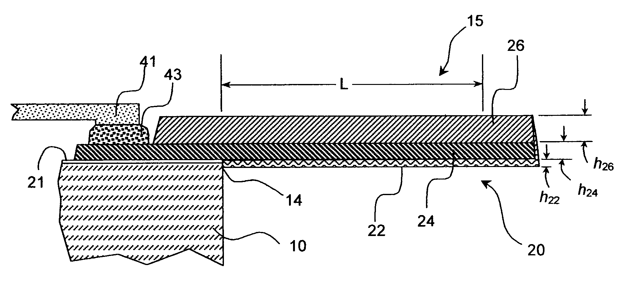
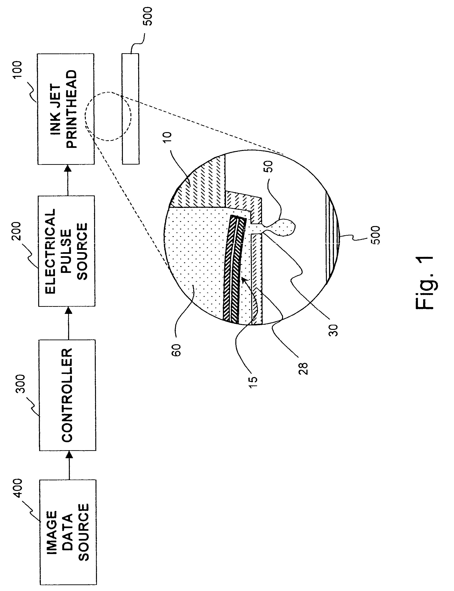
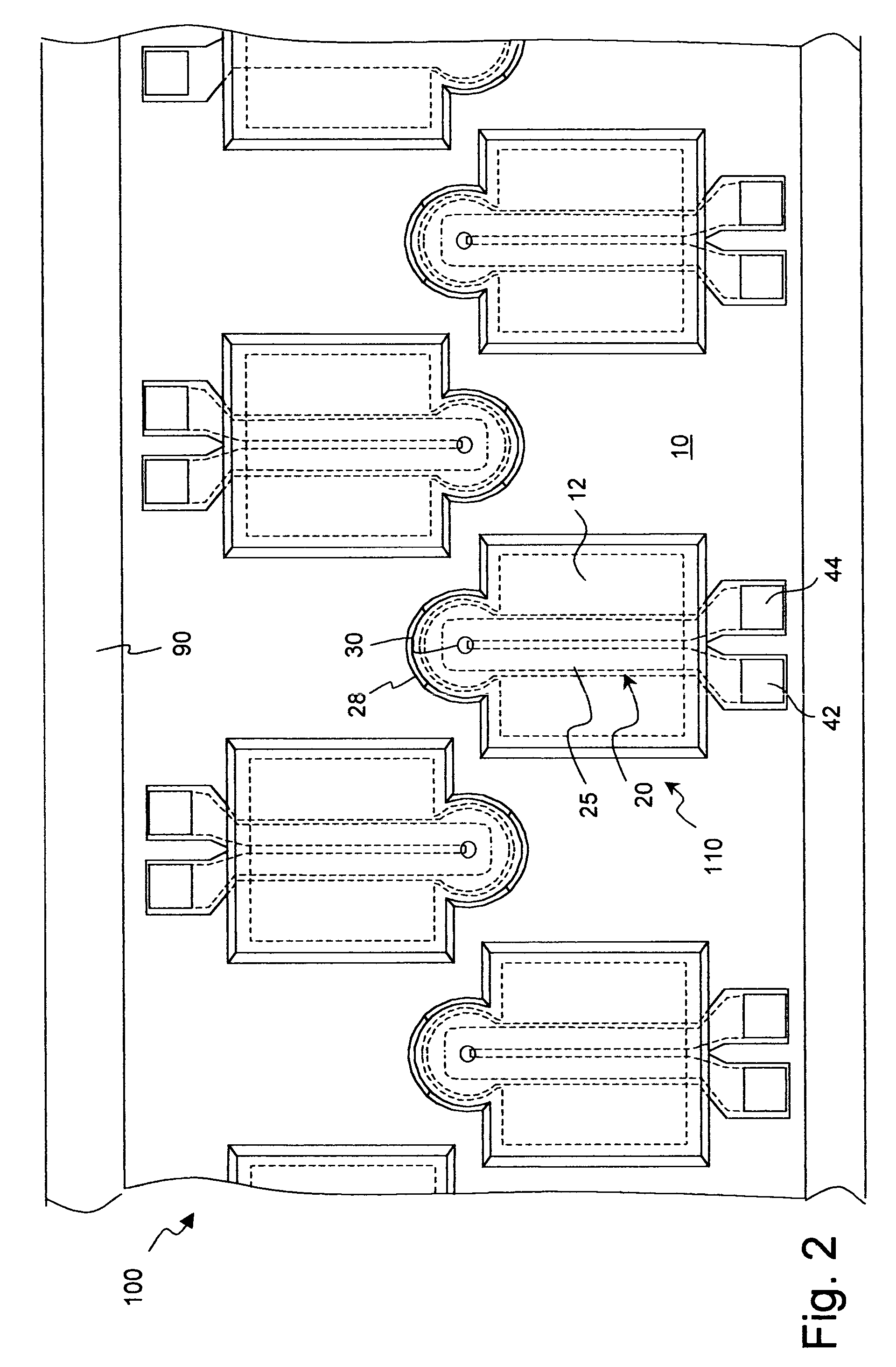
[0035]As described in detail herein below, the present invention provides apparatus for a drop-on-demand liquid emission device. The most familiar of such devices are used as printheads in ink jet printing systems. Many other applications are emerging which make use of devices similar to ink jet printheads, however which emit liquids other than inks that need to be finely metered and deposited with high spatial precision. The terms ink jet and liquid drop emitter will be used herein interchangeably. The inventions described below provide drop emitters based on thermo-mechanical actuators that are configured so as allow the actuator to be operated at high temperatures without subjecting the working liquid to temperatures which would degrade or vapori...


PUM


Abstract

An apparatus for a liquid drop emitter, especially for use in an ink jet printhead, is disclosed. A chamber filled with a liquid, a nozzle and a thermo-mechanical actuator, extending into the chamber from at least one wall of the chamber is disclosed. A movable element of the thermo-mechanical actuator is configured with a bending portion which bends when heated. The bending portion comprises a first layer having first and second sides, constructed of a first material having a high coefficient of thermal expansion, a second layer, attached to the second side of the first layer, and a third layer, attached to the first side of the first layer, constructed of a third material having a low thermal conductivity and a low Young's modulus. Apparatus is adapted to apply heat pulses to the bending portion resulting in rapid deflection of the movable element, ejection of a liquid drop, without degradation or vaporization of the liquid. The third material may be an organic polymer having a Young's modulus less than 10 GPa and thermal conductivity less than 1 W / (m ° K), for example PTFE, teflon.

Description

FIELD OF THE INVENTION[0001]The present invention relates generally to micro-electromechanical devices and, more particularly, to thermally actuated liquid drop emitters such as the type used for ink jet printing.BACKGROUND OF THE INVENTION[0002]Micro-electro mechanical systems (MEMS) are a relatively recent development. Such MEMS are being used as alternatives to conventional electro-mechanical devices as actuators, valves, and positioners. Micro-electromechanical devices are potentially low cost, due to use of microelectronic fabrication techniques. Novel applications are also being discovered due to the small size scale of MEMS devices.[0003]Many potential applications of MEMS technology utilize thermal actuation to provide the motion needed in such devices. For example, many actuators, valves, and positioners use thermal actuators for movement. In some applications the movement required is pulsed. For example, rapid displacement from a first position to a second, followed by res...

Claims


Application Information

Patent Timeline
Patent Type & Authority Patents(United States)
IPC IPC(8): B41J2/04B41J2/14B41J2/16
CPCB41J2/14427B41J2/1628B41J2/1648B41J2/1645B41J2/1646B41J2/1639
Inventor CABAL, ANTONIOLEBENS, JOHN A.POND, STEPHEN F.
Owner EASTMAN KODAK CO
Why Eureka
Try Eureka