Method for calibrating a model of in-situ formation stress distribution

Inactive Publication Date: 2006-05-11
EXXONMOBIL UPSTREAM RES CO
View PDF8 Cites 79 Cited by
  • Summary
  • Abstract
  • Description
  • Claims
  • Application Information

AI Technical Summary

Benefits of technology

[0032] (k) obtaining the substantially calibrated numerical model provided that D1 is acceptable for the formation-stress analysis d

Problems solved by technology

Many practical geomechanical problems require an estimate of the stresses in a formation beneath the earth's surface, whether the formation lies beneath a mass of land, water, or both land and water.
Unfortunately, however, field stress measurements taken at one point in a formation can provide only a limited understanding, if any, of the stress distribution throughout the formation of interest.
So, it has been difficult to determine, with reasonable accuracy and resolution, the stresses at other points in the formation, outside the area in which actual field stress measurements were obtained.
Field stress measurements taken in one region of a formation have been difficult to extrapolate to other points in the formation because the distribution of stresses in the formation can depend heavily on topography, far-field tectonic forces and local geologic history, among other factors.
Consequently, before Applicants' invention, methods used to estimate the distribution of stresses in a formation have produced relatively inaccurate and unresolved stress values for other points in the formation outside the area in which actual field stress measurements were obtained.
However, such an approximation implicitly neglects variability in rock properties and topography throughout a formation, frequently found in the formations of interest, and past geologic processes (e.g., deposition, ero

Method used


Image

  • Method for calibrating a model of in-situ formation stress distribution
  • Method for calibrating a model of in-situ formation stress distribution
  • Method for calibrating a model of in-situ formation stress distribution

Examples


example 1

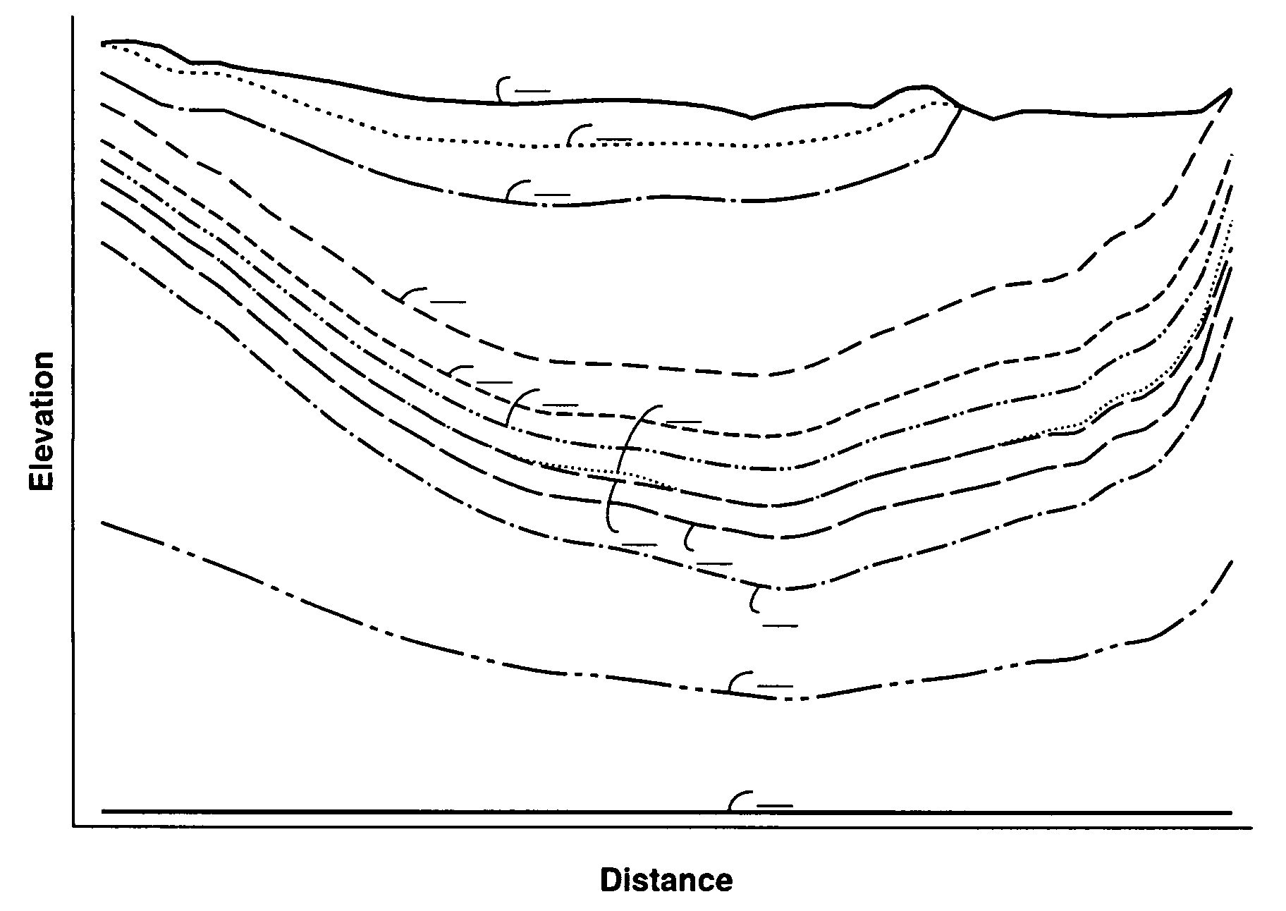
[0141] The topography and nine subsurface horizons (i.e., the top of each strata) for the formation of interest were obtained from company data and published interpretations of the region from the US Geological Survey. FIG. 4 is a graphical representation of one structural cross-section of the formation. The top line, labeled “Topo,” represents the topography elevation along the cross-section. The nine subsurface horizons for nine strata in the formation are labeled Horizon 2 through Horizon 10.

[0142] To provide a flat bottom surface, on which kinematic constraints could be applied in the numerical modeling, two additional strata were added. The horizon of the near-bottom stratum is labeled Horizon 11, while the flat bottom horizon of the bottom stratum is labeled “Bottom”.

[0143] The gross lithology for each strata was interpreted from well log data and outcrop studies. The interpreted gross lithology for each stratum is described in terms of compositional percentage of end-member...

example 2

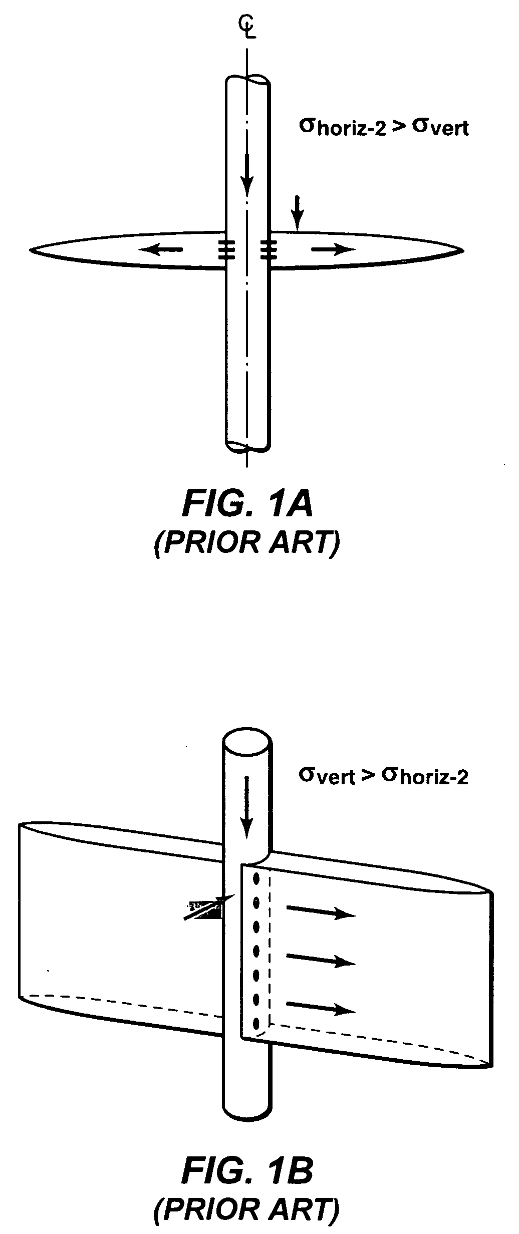
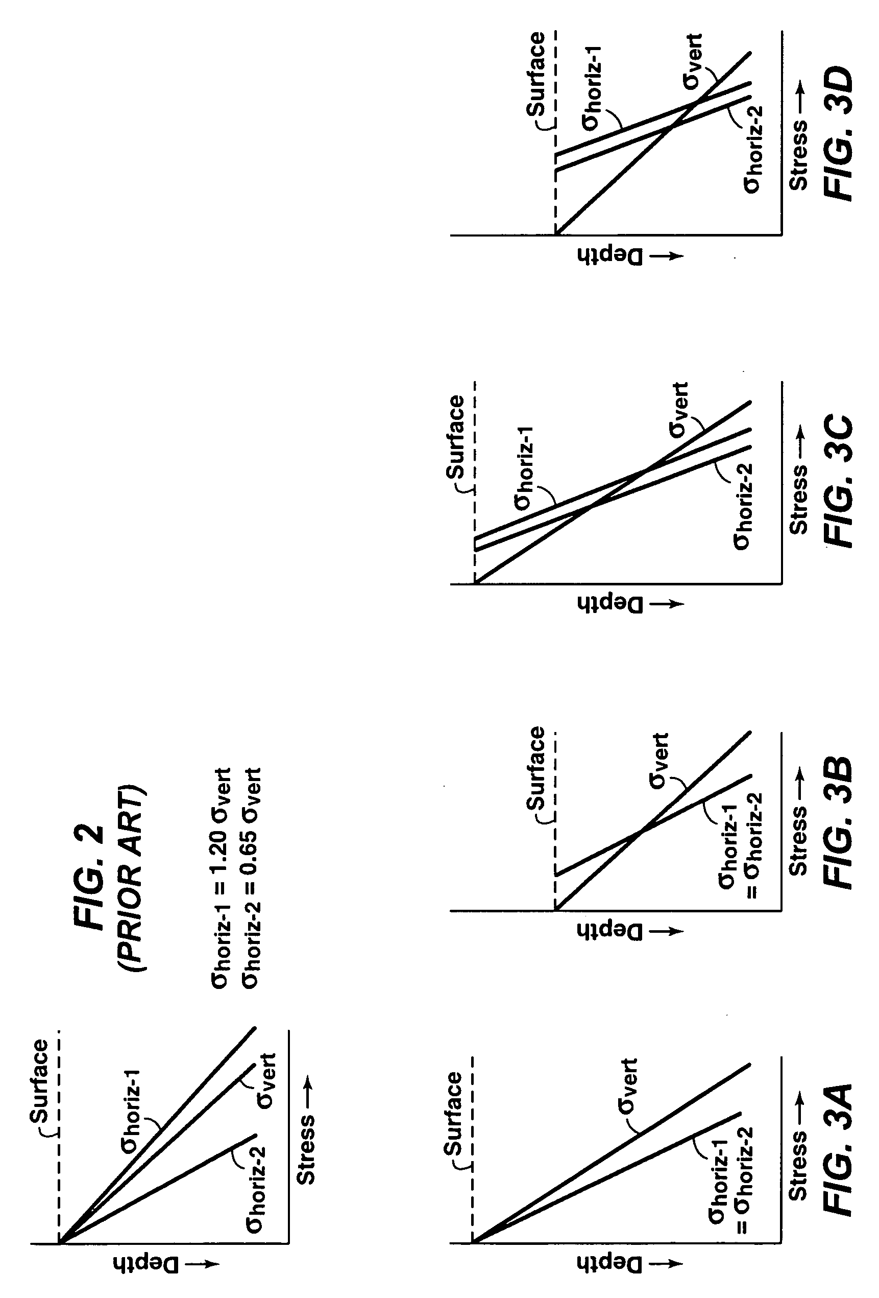
[0172] The calibrated model from Example 1 was used to illustrate one example application. In particular, this example was conducted to estimate the fracture orientation transition elevation for the entire formation of interest. Specifically, above the fracture orientation transition elevation, induced fractures will tend to be substantially horizontal in orientation, while below the transition elevation, induced fractures will tend to be oriented substantially vertically. The formation-wide transition elevation estimate includes the effects of topography, tectonics, and recent erosion. The transition elevation estimates are useful for assessing, at any point of interest in the formation, whether the formation's stress state, at that point, is more likely to favor either a substantially horizontal or vertical fracture orientation.

[0173] Stress profiles were extracted from the modeled formation-stress analysis. The elevations where values for σvert and σhoriz-2 were equal were recor...


PUM


Abstract

A method for producing a substantially calibrated numerical model, which can be used for calculating a stress on any point in a formation, accounts for a formation's geologic history using at least one virtual formation condition to effectively “create” the present-day, virgin stress distribution that correlates, within acceptable deviation limits, to actual field stress measurement data obtained for the formation. A virtual formation condition may describe an elastic rock property (e.g., Poisson ratio, Young's modulus), a plastic rock property (e.g., friction angle, cohesion) and/or a geologic process (e.g., tectonics, erosion) considered pertinent to developing a stratigraphic model suitable for performing the desired stress analysis of the formation.

Description

CROSS REFERENCE TO RELATED APPLICATIONS [0001] This application claims the benefit of U.S. Provisional Application No. 60 / 626,814, filed Nov. 10, 2004.FIELD OF THE INVENTION [0002] The present invention relates to the field of stress analysis and, in particular, to a method of calibrating a numerical model used for calculating stress on any point in a geologic formation. BACKGROUND OF THE INVENTION [0003] Many practical geomechanical problems require an estimate of the stresses in a formation beneath the earth's surface, whether the formation lies beneath a mass of land, water, or both land and water. Often, when time and costs are not a limiting factor, the stresses at a particular area of interest in a particular formation can be assessed using field stress measurement methods such as hydraulic fracturing methods, borehole ellipticity / breakout methods, formation integrity tests, and mini-frac tests, among other methods. Unfortunately, however, field stress measurements taken at on...

Claims


Application Information

Patent Timeline
IPC IPC(8): G06G7/48
CPCE21B49/006
Inventor SYMINGTON, WILLIAM A.YALE, DAVID P.
Owner EXXONMOBIL UPSTREAM RES CO
Why Eureka
Try Eureka