Phased array ultrasonic examination system and method

a phased array and ultrasonic technology, applied in the direction of instruments, specific gravity measurement, measurement devices, etc., can solve the problems of physical flaws of solid objects such as mechanical equipment, loss of property or personal injury, and inability to detect flaws through visual inspection, so as to achieve complete and effective inspection and readily identify flaws

Inactive Publication Date: 2014-06-10
TEJAS TESTING & INSPECTION
View PDF33 Cites 16 Cited by
  • Summary
  • Abstract
  • Description
  • Claims
  • Application Information

AI Technical Summary

Benefits of technology

[0016]The objects described above and other advantages and features of the invention are incorporated in a method and a system that provides for adapting phased array ultrasound testing techniques for inspecting raw material in bulk, particularly seamless mechanical tubing and piping, which complies with present-day industry codes and standards but allows for much more robust and thorough flaw detection capability.
[0019]The flaw detector is configured to display the A-scan on-screen concurrently with the S-scan. The flaw detector is set so that it produces a beam which sweeps from 30 degrees to 70 degrees through the material to be tested. A-scan data that corresponds with the traditional preferred inspection incidence angle is selected, and reject levels are set to 0% to meet current inspection standards. The wedge is placed on the test piece and then moved spirally in a circumferential direction to detect longitudinal defects. The inspection is then performed in the opposite direction, resulting in a complete bi-directional circumferential inspection. Additionally, to further ensure a complete and effective inspection, the scanning is preferably performed axially. The S-scan data, displayed concurrently with the A-scan data for the preferred incidence angle, allows for detection of flaws that might otherwise be undetectable using only A-scan data. A palette adjustment feature of the flaw detector is utilized to remap the colors assigned to lower intensity return values so that they are not displayed on the S-scan. The result de-clutters S-scan data without filtering A-scan data, allowing the operator to more readily identify flaws using S-scan data while concurrently meeting A-scan inspection code requirements.

Problems solved by technology

Solid objects such as mechanical equipment may sometimes have physical flaws.
Otherwise, the mechanical equipment may fail causing loss of property or personal injury.
However, such flaws are often undetectable via visual inspection.
However, if the flaw in the material is not generally perpendicular to the sound path, the flaw may go undetected.
However, a single 45 degree angle cannot detect all of the flaws due to geometry aspects of the ultrasonic waves.
The traditional A-scan flaw detectors cannot electronically control the angle at which the sound is projected.
Weld joints may be particularly problematic.
Welds are known to be subject to many types of defects that can orient themselves in unpredictable ways.
Although PAUT is often used in weld inspection, it has not found common use for inspection of raw tubular stock, particularly due to several shortcomings.

Method used


Image

  • Phased array ultrasonic examination system and method
  • Phased array ultrasonic examination system and method
  • Phased array ultrasonic examination system and method

Examples


Embodiment Construction

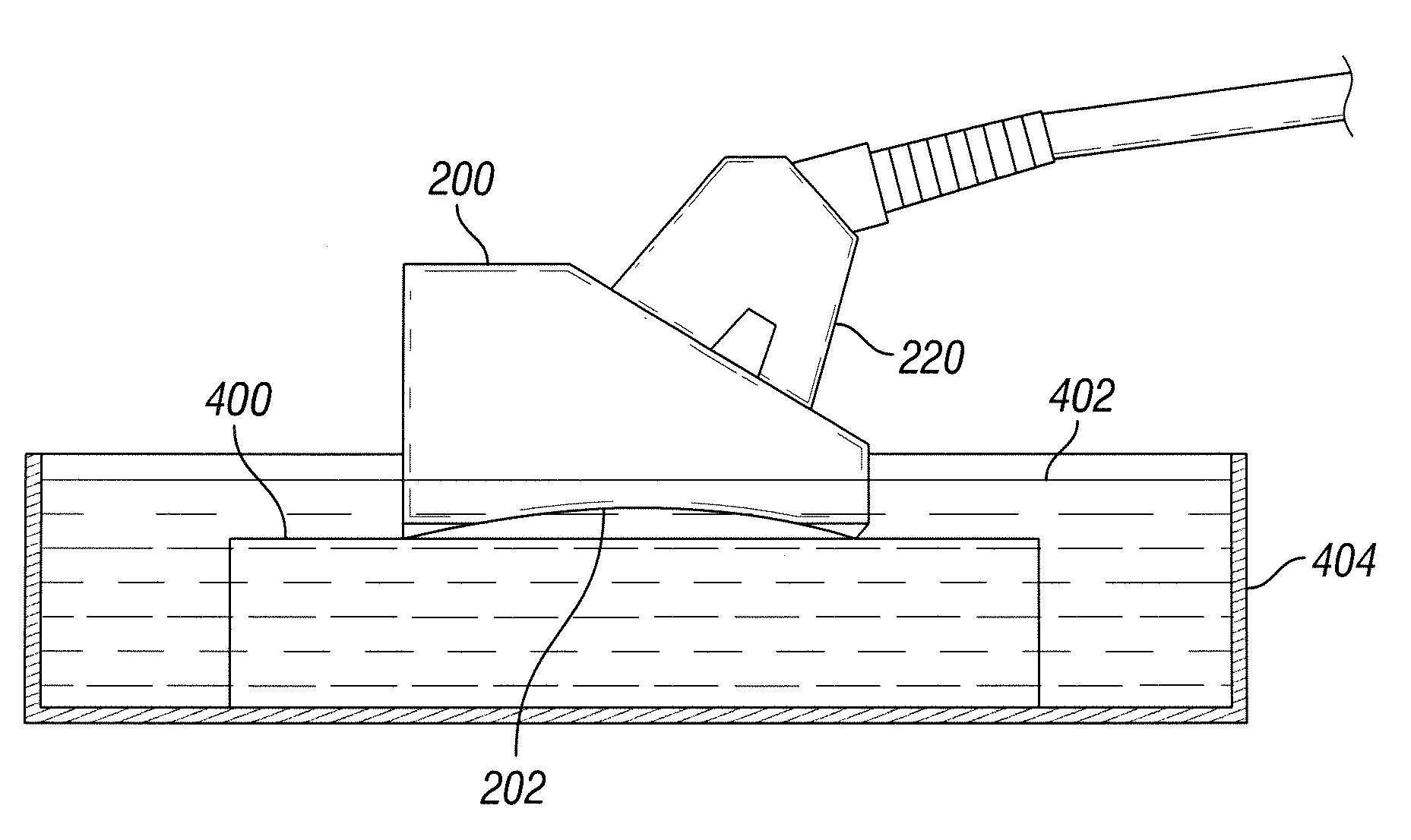
[0034]The current disclosure describes a method and apparatus for adapting PAUT for use in inspecting raw material in bulk, particularly seamless mechanical tubing and piping, which complies with present-day industry codes and standards (that currently provide only for A-scan processes) but allows for much more robust and thorough flaw detection capability. The present disclosure exceeds current code and industry standards by providing exceptional flaw detection not otherwise available using known methods.

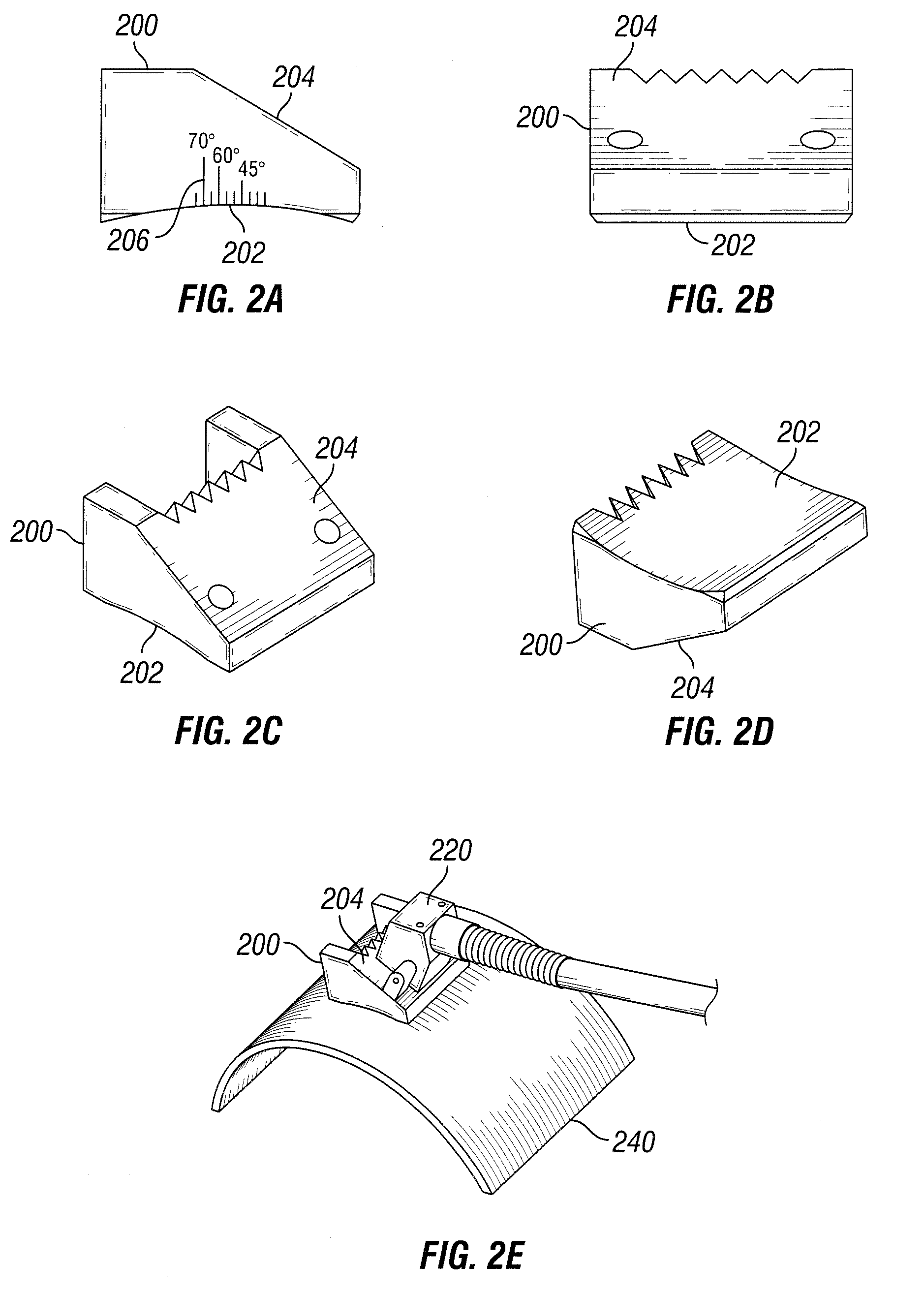
[0035]The basic equipment required to practice the invention includes a PAUT flaw detector, a PAUT transducer, and an angled wedge. Currently, there are no known engineering standards developed by ASME, ASIM or API for the application of PAUT to bulk tubular goods. Although some adjustments will be made to the equipment for adapting it for use with bulk tubular goods, many of the requirements of ASTM E2700 for welds remain applicable.

[0036]The flaw detector of the present disclosur...


PUM

PropertyMeasurementUnit
incidence anglesaaaaaaaaaa

Abstract

A method and apparatus for phased array ultrasound testing of piping that complies with present-day codes but allows more thorough flaw detection capability. A tapered wedge with a concave face is calibrated by submerging the wedge under sonic coupling fluid, thereby allowing sonic coupling of the concave wedge face to a flat reference plate with minimal error. The flaw detector is configured to display A-scan and S-scan data concurrently and to sweep between 30-70 degrees. A-scan data corresponding with conventional preferred inspection incidence angle is selected, and reject levels are set to 0% to meet current inspection standards. S-scan data allows for detection of flaws that might otherwise be undetectable using only A-scan data. A palette adjustment feature remaps the colors assigned to lower intensity return values so that they are not displayed on the S-scan, thereby de-cluttering sectorial data without filtering A-scan data.

Description

CROSS REFERENCE TO RELATED APPLICATION[0001]This application is based upon provisional application 61 / 516,803 filed on Apr. 8, 2011, which is incorporated herein by reference and the priority of which is claimed.BACKGROUND OF THE INVENTION[0002]1. Field of the Invention[0003]The present disclosure relates to a system and method for examining and testing solid objects using non-destructive ultrasonic phased arrays. More particularly, the present disclosure relates to a system and method for examining and testing seamless mechanical tubing and piping.[0004]2. Background Art[0005]Solid objects such as mechanical equipment may sometimes have physical flaws. Flaws may either occur during the manufacturing stage or at a later time due to external factors. It is important to find such flaws prior to the mechanical equipment being put into use. Otherwise, the mechanical equipment may fail causing loss of property or personal injury. However, such flaws are often undetectable via visual insp...

Claims


Application Information

Patent Timeline
Patent Type & Authority Patents(United States)
IPC IPC(8): G01N29/04
CPCG01N2291/102G01N29/221G01N29/262G01N2291/2634
Inventor TIPPIT, JR., WILLIAM CAROLLEWIS, C. MICHAEL
Owner TEJAS TESTING & INSPECTION
Why Eureka
Try Eureka