Luminary product

a technology for luminary products and luminaires, applied in non-electric lighting, light and heating equipment, display means, etc., can solve the problems of difficult and costly to decorate the outer surface of a luminary product or its holder, many known techniques do not provide flexibility in production to quickly and easily change the particular decorative design, and limit the ability to cost-effectively provide a variety of designs

Inactive Publication Date: 2006-03-14
SC JOHNSON & SON INC
View PDF145 Cites 49 Cited by
  • Summary
  • Abstract
  • Description
  • Claims
  • Application Information

AI Technical Summary

Benefits of technology

[0019]For example, a heat-shrinkable film, prior to application to the outer surface of a candle holder, may be printed with a background layer, or a single design or pattern of conventional ink, and a second pattern may be applied over the first, in registry therewith so as to produce a desired pattern, to provide a specific effect upon heating of the heat-shrinkable film by the burning of the candle within the candle holder. The aesthetic effect of a flickering flame through such heat-shrinkable films is enhanced by virtue of the candle holder of a specific form or configuration, especially a candle holder having the hammered texture. This hammered texture on the inner surface of the candle holder provides a pleasing effect, as the light is refracted in differing patterns when it passes through the glass and is refracted differently at various points upon the glass surface.
[0020]Accordingly, in one aspect, a decorated luminary product comprises a candle, a candle holder suitable for containing the candle, the candle holder having an inner surface and an outer surface, and a web of a heat shrunk polymer encasing the outer surface of the candle holder. The web includes a decorative feature. At least one of the inner surface and the outer surface of the candle holder has a hammered texture and the decorative feature of the web is located so as to cooperate with light emitted by the candle in the candle holder to augment a visual effect when the candle is lit.
[0021]Another aspect of the invention relates to a decorated luminary product comprising a candle, a candle holder selected from the group consisting of chimneys, globes and jars, suitable for containing a candle, the candle holder having an inner surface and an outer surface, and a web of a heat shrunk polymer encasing the candle holder, the web including a decorative feature. At least one of the inner surface and the outer surface of the candle holder has a hammered texture and the decorative feature of the web is located so as to cooperate with light emitted by the candle in the candle holder to augment a visual effect when the candle is lit.
[0023]The novel luminaries obtained by the practice of this invention produce visual effects that are inexpensive, visually pleasing, change throughout the duration of the burning of the candle, and are capable of being provided with a large variety of designs, such as seasonal or holiday themes. This is particularly noticeable in the case of a burning candle, where the height of the candle flame varies as the candle is burned, changing the angle at which the light of the candle flame impinges upon the surface of the candle holder.

Problems solved by technology

However, it can be difficult and costly to decorate the outer surface of a luminary product or its holder.
Also, many known techniques do not provide flexibility in production to rapidly and easily change the particular decorative design.
This limits the ability to cost-effectively provide a variety of designs, or to tailor the designs to the desires of the consumer, or to a specific season, event, motif, holiday or the like, or to provide a product having a decorative effect which changes in accordance with whether the luminary is itself lit or unlit.

Method used


Image

  • Luminary product
  • Luminary product
  • Luminary product

Examples


Embodiment Construction

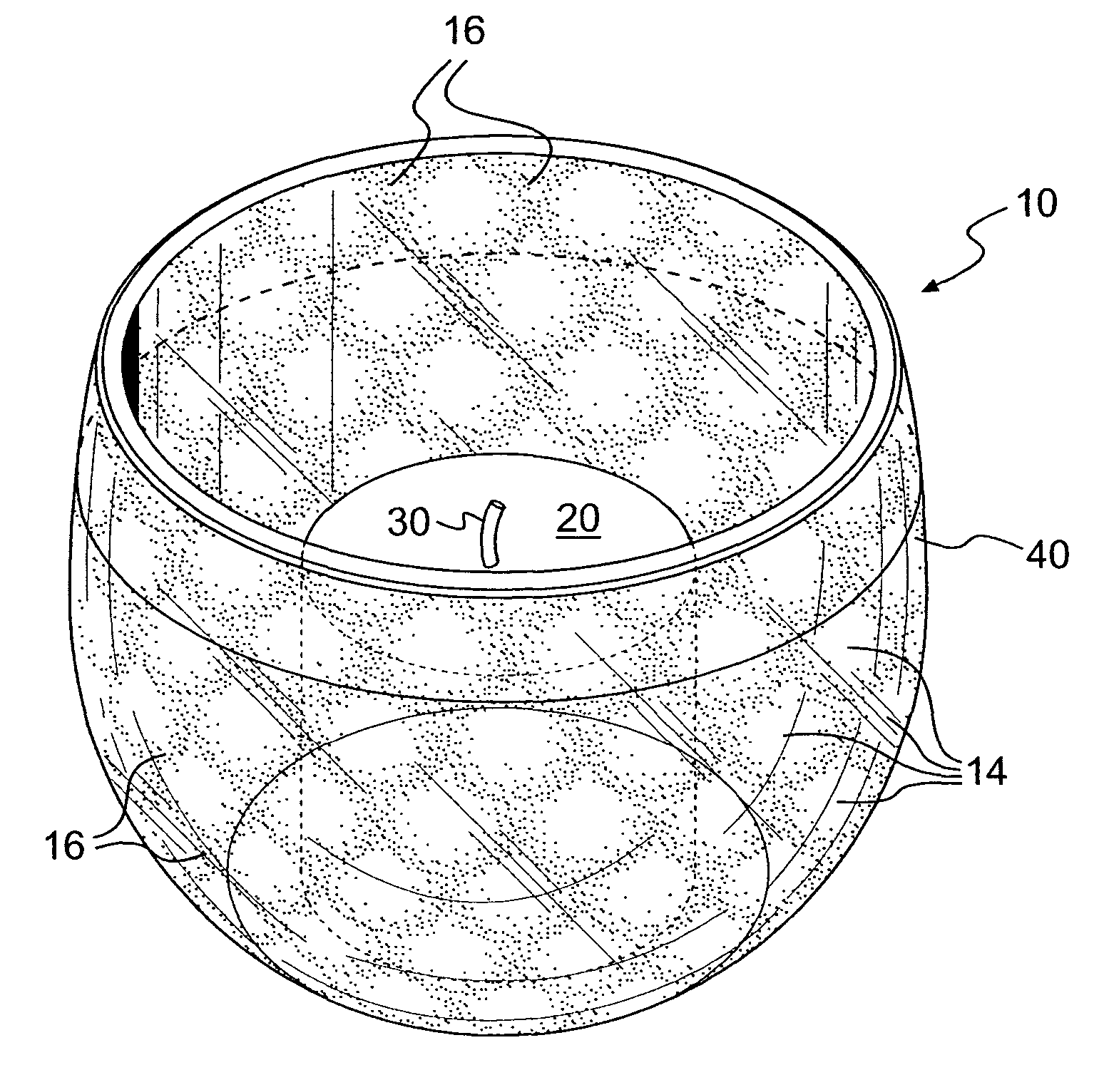
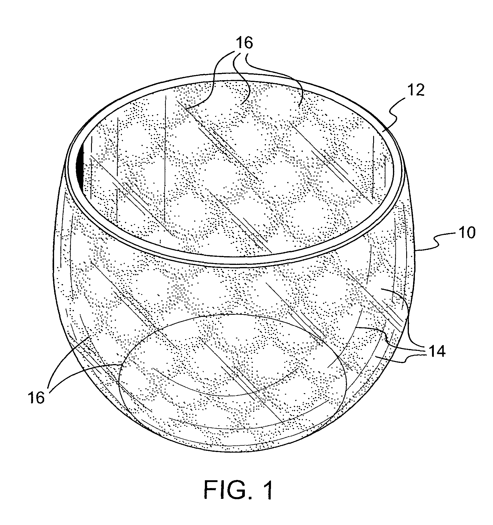
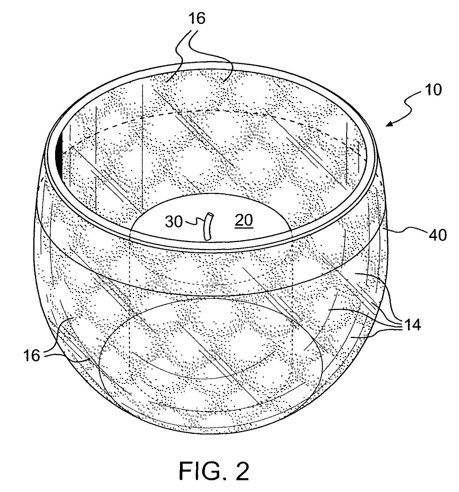
[0028]As shown in FIGS. 1 through 3, our invention comprises a candle holder 10 preferably filled with a combustible material 20, such as wax, through which a wick 30 is provided to create a candle. The combustible material 20 and wick 30, in the form of a candle, may be free standing as shown in FIG. 2, or poured in as shown in FIG. 3. In either case, the top surface of the combustible material is disposed below the upper rim 12 of the candle holder 10, such that when the wick 30 is lit, thereby burning the combustible material 20 via the wick 30 and generating a continuous flame about the wick 30, light emanating from the flame is refracted by at least the portion of the candle holder 10 extending between the top surface of the combustible material 20 and the upper rim 12.

[0029]As shown schematically in FIGS. 1 through 3, the candle holder 10 includes an inner surface having a hammered texture (such hammered texture need not resemble the regular pattern depicted in these figures, ...


PUM

PropertyMeasurementUnit
height shrinkageaaaaaaaaaa
temperaturesaaaaaaaaaa

Abstract

A decorated luminary product includes a candle holder containing a candle, wherein at least one of the inner surface and the outer surface of the candle holder has a hammered texture such that light passing through the candle holder varies substantially as a result of variation of refraction of the light. A decorative web of a heat-shrinkable polymer may be heat shrunk to conform to the outer surface of the candle holder. The web is decorated with an ink or pigmentation to cooperate with light and / or heat emitted by burning the candle, so as to provide a pleasing visual effect when the candle is burned, while the hammered texture of the candle holder causes variations in the refraction of light emitted from the candle, causing further visual effects. The refraction of light caused by the hammered texture of the candle holder also provides aesthetically pleasing effects when the candle is unlit, due to variations in the image on the web resulting from variation in the light observed passing through the candle holder.

Description

BACKGROUND OF THE INVENTION[0001]1. Technical Field[0002]Our invention, in general, relates to decorated luminary products, and more particularly to luminary products decorated by the use of transparent jars having a hammered texture forming an inner surface thereof, and also preferably including a decorative film wrapped around the jar. The hammered texture provides for refraction of the light emitted by, for example, a candle in the luminary product, in such a manner as to provide a varying light show as a result of the flickering of the candle flame.[0003]2. Background Information[0004]Luminary products come in many shapes, sizes, and designs. Such luminary products are typically wick based and burn a hydrocarbon-based fuel, and include such items as candles, oil lamps or lanterns.[0005]In many cases, it is desirable to decorate the luminary products to improve their aesthetics, both when the luminary is unlit and when lit. However, it can be difficult and costly to decorate the ...

Claims


Application Information

Patent Timeline
Patent Type & Authority Patents(United States)
IPC IPC(8): F21V9/16A61L9/03B44C1/10B44C5/00B44F1/06B44F1/10C11C5/00F21S10/04F21S13/12F21V3/04F21V35/00F21V37/00
CPCA61L9/03B44C1/10B44C5/00B44C5/005B44F1/06B44F1/10F21S13/12F21V3/04F21V35/00C11C5/008Y10S362/806F21S10/04F21V37/0095
Inventor MORRIS, LEGAL REPRESENTATIVE, MELISSA D.DELCOURT, FRANCOIS P.MICELE, JR., DECEASED, ANTHONY G.
Owner SC JOHNSON & SON INC
Why Eureka
Try Eureka