
Driving operation assisting method and system

a technology of driving operation and assisting method, which is applied in the direction of anti-collision system, non-deflectable wheel steering, underwater vessels, etc., can solve the problems of user's inability to make good use of driving know-how, user's experience of vehicle size also changes, and the user has to take a considerable amount of practice to be skilled in such operations, so as to reduce the burden of users and improve the convenience of users

Inactive Publication Date: 2006-03-14
PANASONIC CORP
View PDF21 Cites 19 Cited by
  • Summary
  • Abstract
  • Description
  • Claims
  • Application Information

AI Technical Summary

Benefits of technology

[0008]An object of the present invention is to provide a driving operation assisting technique so as to further improve the user's convenience and reduce the user's burden with.
[0010]According to this invention, only by specifying the end position of a predetermined series of driving operations to be performed, the start position of the driving operation can be automatically obtained, thereby reducing the amount of time required before starting the driving operation.
[0012]It is preferred that in the first step, the end position specified by the user is taken as an input when the vehicle is in a vicinity of the end position. Thus, it is possible to more precisely specify the end position to be the target position.
[0015]According to this invention, a prescribed trace of the vehicle can be input through a pointer input operation on the screen of the display unit, thereby significantly facilitating the selection of the prescribed movement pattern.
[0017]According to this invention, the circumscribed area trace of space where the entire vehicle passes is displayed as an image, whereby the user can more precisely determine whether a part of the vehicle, such as a bumper, which extends beyond the tire will contact an obstacle.

Problems solved by technology

However, it takes the user a considerable amount of practice to be skilled in such operations.
Moreover, when the size, etc., of the vehicle to be driven changes, the sense of the size of the vehicle also changes, whereby the user cannot make good use of the driving know-how the user has built up while getting skilled in the operations with the previous vehicle.
Now, in the case of a parking operation, it is generally difficult to complete the driving operation while keeping the rudder angle of the steering wheel at a constant angle from the beginning of the operation, except for cases where there is no obstacle at all around the vehicle.
In other words, in the case of parallel parking, it is difficult to park the vehicle while keeping the steering rudder angle at a constant angle.
Moreover, with the conventional system, if the driver moves the steering wheel even by a slight angle, a vehicle movement path is re-estimated in response to the slight change in the rudder angle, and the re-estimated path is displayed, which may confuse the driver.
Furthermore, since an actual vehicle body has some parts overhanging from the tires, the body may possibly contact an obstacle even if the tire trace does not interfere with the obstacle.
Thus, in the prior art, it is difficult to precisely determine whether the vehicle parts extending beyond the tires will contact an obstacle.

Method used


Image

  • Driving operation assisting method and system
  • Driving operation assisting method and system
  • Driving operation assisting method and system

Examples


first embodiment

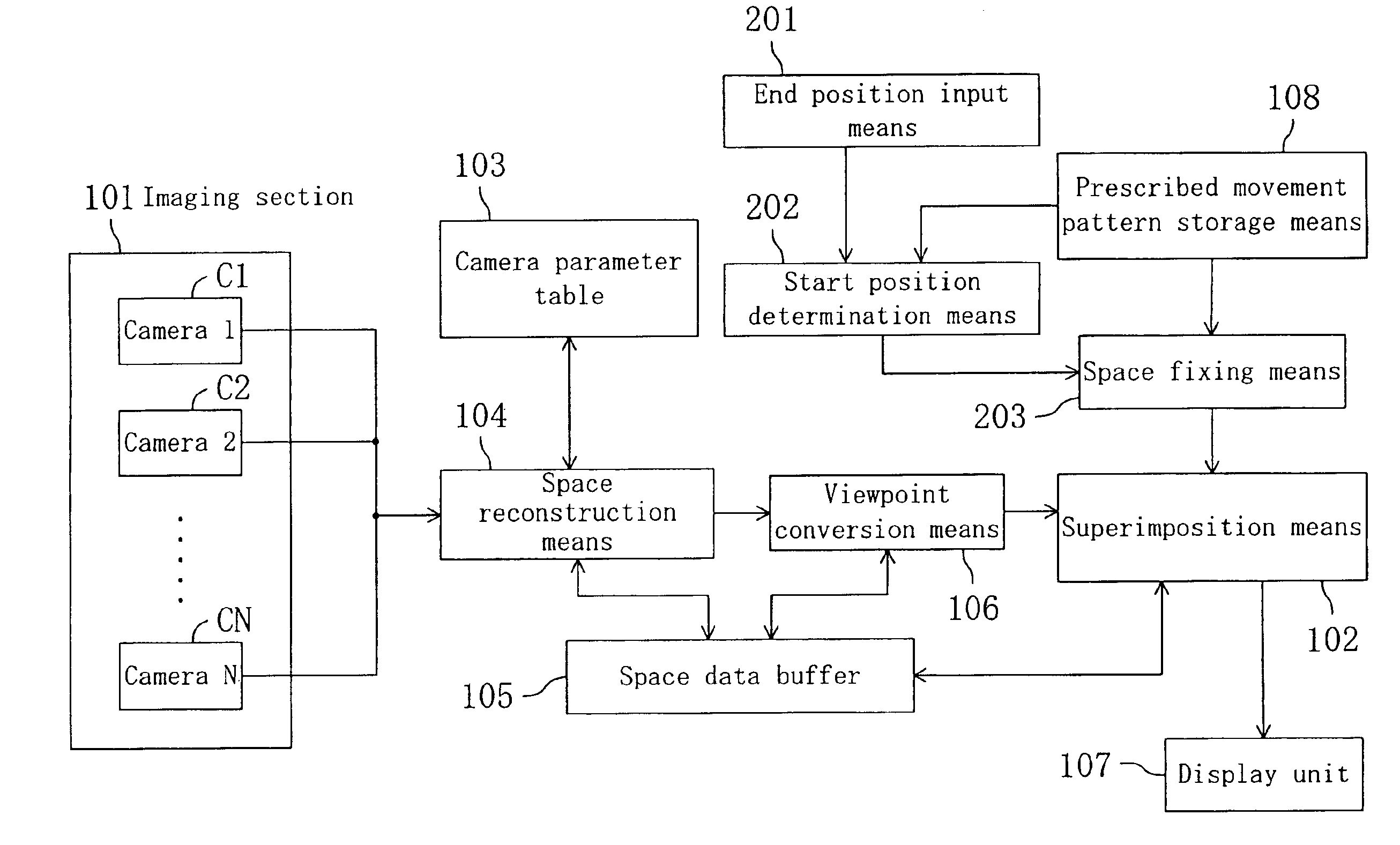
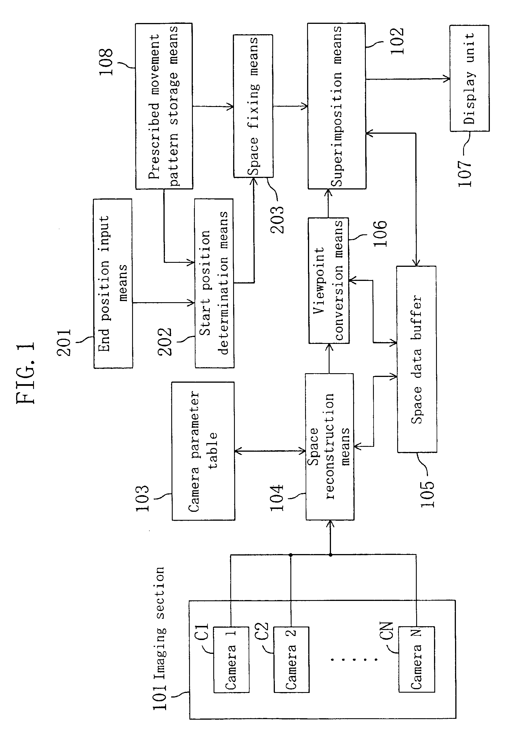
[0049]FIG. 1 is a block diagram illustrating a configuration of a driving operation assisting system according to the first embodiment of the present invention. The driving operation assisting system of the present embodiment primarily aims to provide an assistance in a driving operation such as perpendicular parking, parallel parking, and the like.

[0050]As illustrated in FIG. 1, the driving operation assisting system of the present embodiment includes: an imaging section 101 having N cameras (cameras C1 to CN); a camera parameter table 103 for storing camera parameters representing the characteristics of the cameras C1 to CN; space reconstruction means 104 for producing space data in which the respective pixels forming the output images from the cameras C1 to CN are correlated to points in a three-dimensional space based on the camera parameters; viewpoint conversion means 106 for producing, as a surrounding condition image, an image as viewed from a predetermined viewpoint by refe...

second embodiment

[0093]FIG. 14 is a block diagram illustrating a configuration of a driving operation assisting system according to the second embodiment of the present invention. The driving operation assisting system of the present embodiment also primarily aims to provide an assistance in a driving operation such as perpendicular parking, parallel parking, and the like. Therefore, in the present embodiment, the elements / functions not specifically described below are assumed to be as those of the first embodiment, and the elements having the same reference numerals as those in FIG. 1 are assumed to have similar functions as those of FIG. 1 unless otherwise indicated. Moreover, it is assumed that each variation described in the first embodiment can be similarly applied to the present embodiment unless otherwise indicated.

[0094]In the present embodiment, surrounding condition imaging means is provided including the imaging section 101, the camera parameter table 103, the space reconstruction means 1...

third embodiment

[0118]FIG. 25 is a block diagram illustrating a configuration of a driving operation assisting system according to the third embodiment of the present invention. In the present embodiment, the elements / functions not specifically described below are assumed to be as those of the first embodiment, and the elements having the same reference numerals as those in FIG. 1 are assumed to have similar functions as those of FIG. 1 unless otherwise indicated. Moreover, it is assumed that each variation described in the first embodiment can be similarly applied to the present embodiment unless otherwise indicated. In the present embodiment, an image processing section is provided including the superimposition means 102 and circumscribed area trace synthesis means 403.

[0119]In the driving operation assisting system of the present embodiment, not only a tire trace TT (shown in broken lines) but also a circumscribed area trace CAT (shown in solid lines) of space where the entire vehicle passes is ...


PUM


Abstract

In a driving operation assisting technique, the burden on a user is reduced. The user is allowed to specify, on an image representing the surrounding conditions around a vehicle, the end position of the vehicle at the end of a predetermined driving operation by using, for example, a pointer. A driving operation assisting system obtains the start position of the driving operation based on a prescribed movement pattern representing the movement of the vehicle in the driving operation, and superimposes the end position on the display image.

Description

BACKGROUND OF THE INVENTION[0001]The present invention relates to a driving operation assisting technique for providing an assistance in a vehicle driving operation.[0002]A common driving operation assisting system in the prior art uses a steering sensor for detecting the rudder angle of the steering wheel so as to estimate the vehicle tire (movement) trace according to the rudder angle of the steering wheel when moving the vehicle backward (see Japanese Laid-Open Patent Publication No. 1-14700). In this system, when moving the vehicle backward, the rear view or the rear-side view is imaged by a camera and displayed, while the vehicle tire trace which is estimated according to the rudder angle of the steering wheel being operated is superimposed on the image.[0003]When using this system, the driving operation is as follows. That is, first, the vehicle is moved to a position where it is likely to be possible to move the vehicle into a parking space with the steering wheel being fixed...

Claims


Application Information

Patent Timeline
IPC IPC(8): B60Q1/48G08G1/16
CPCB62D15/027G08G1/161G08G1/16B62D15/0285B60T2201/10G08G1/165G08G1/168
Inventor ISHII, HIROFUMIOKAMOTO, SHUSAKUNOBORI, KUNIONAKAGAWA, MASAMICHI
Owner PANASONIC CORP
Learn More