Image quality correcting circuit

a technology of image quality and correcting circuit, which is applied in the field of image quality correction circuit, can solve the problems of poor resolution on the bright side, poor resolution on the dark side, and inability to improve according, so as to simplify and simplify the effect of the composition of the occurrence frequency counter

Inactive Publication Date: 2006-03-14
CANON KK
View PDF5 Cites 22 Cited by
  • Summary
  • Abstract
  • Description
  • Claims
  • Application Information

AI Technical Summary

Benefits of technology

The technical effect described in this patents relates to simplifying the calculation process used during the detection phase of any event count ratecounter(s), which helps reduce complexity while maintain accuracy. It achieves these improvements through adding specific detectors called discriminants at different stages of resolution conversion. These discriminant circuits can be added without affecting other components such as integrals. This allows us to create variations over time based upon changes detected values rather than just fixed ones. Overall, it provides improved performance and efficiency in image processing systems.

Problems solved by technology

The technical problem addressed in this patent is the lack of consideration for the luminance level histogram in image quality correcting circuits, which can result in poor display quality and resolution on both bright and dark sides of the image. The proposed solution aims to provide an image quality correcting circuit that can correct all types of images based on the best correcting characteristic corresponding to the occurrence frequency of each luminance level.

Method used


Image

  • Image quality correcting circuit
  • Image quality correcting circuit
  • Image quality correcting circuit

Examples


first embodiment

[0042]The image quality correcting circuit as the present invention will be described in the following referring to FIGS. 6, 7 and 8.

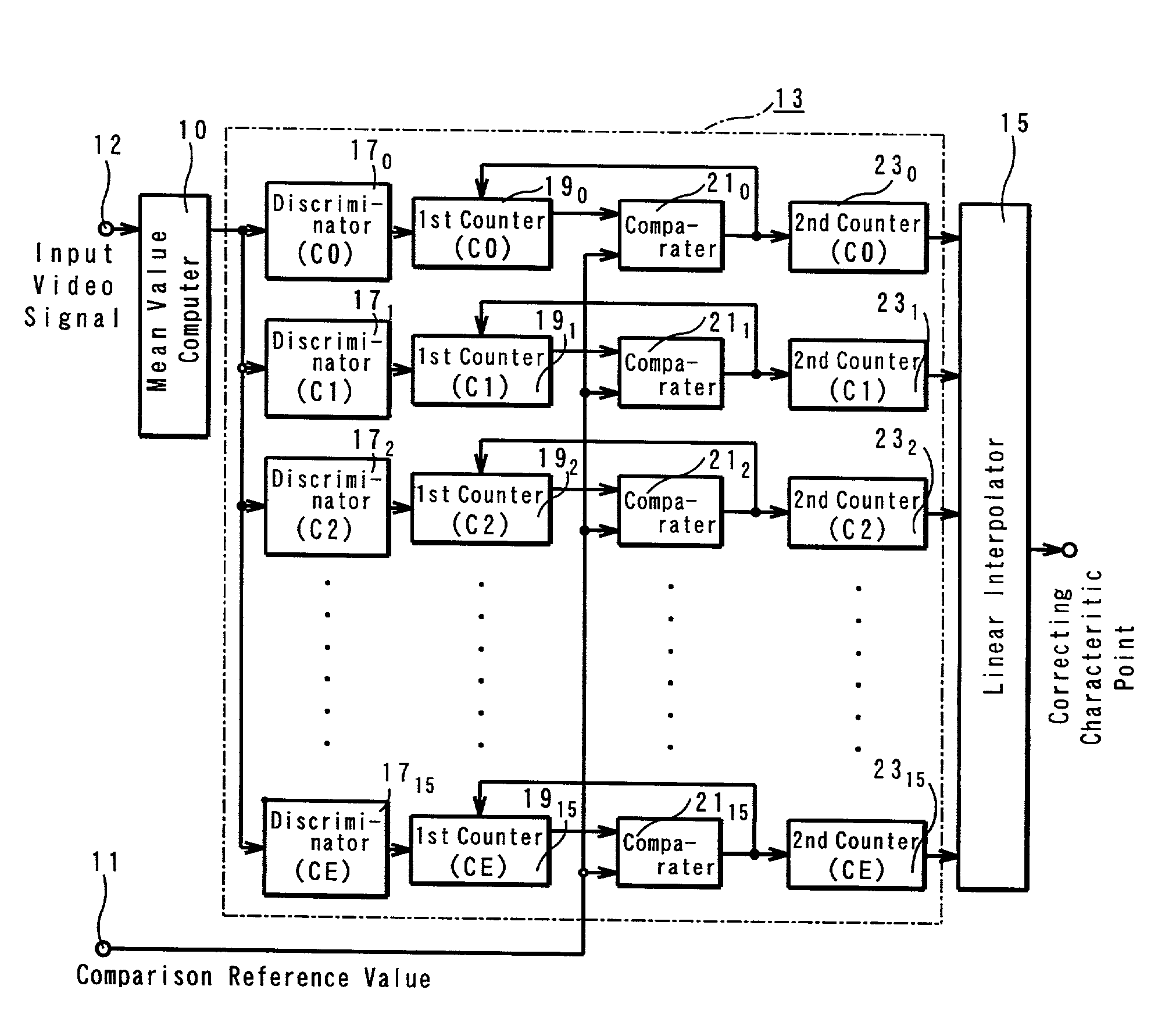
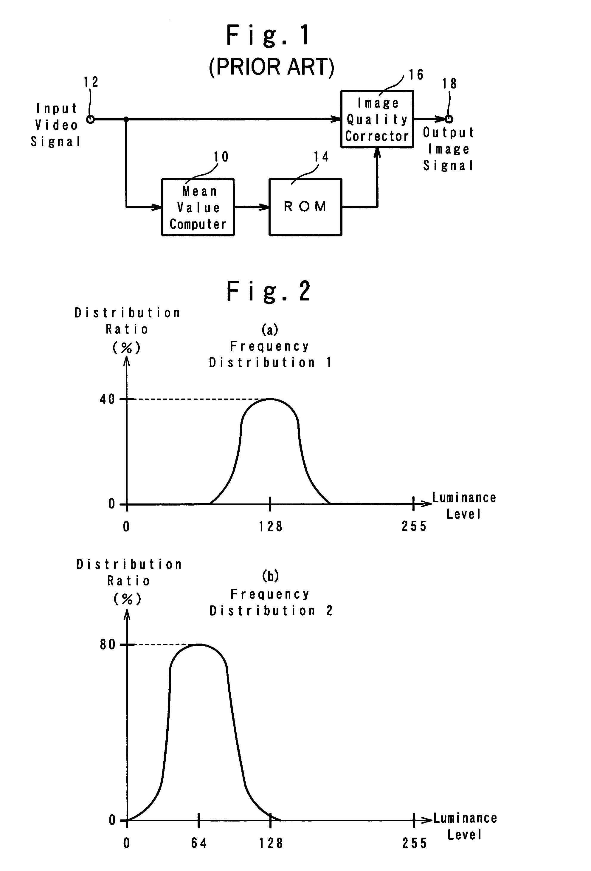
[0043]In FIG. 6, numeral 12 represents the video signal input terminal whereto the video signal is to be inputted; 10, the mean value computer for computing the mean value of the luminance levels at m number of points (m=an integer of 2 or more); 13, the occurrence frequency counter for sequentially counting the occurrence frequency of previously set different luminance levels beginning from 0 level; 11, the comparison reference value input terminal; 15, the linear interpolator for obtaining correcting characteristic point based on the occurrence frequency data; 16, the image quality corrector for correcting image quality based on the linear interpolation; 18, the video signal output terminal for outputting a corrected video signal.

[0044]FIG. 7 is a circuit diagram of the occurrence frequency counter showing a greater detail.

[0045]The mean value comput...

second embodiment

[0062]Next, the present invention will be described referring to FIGS. 9, 10 and 11.

[0063]In FIG. 9, the video signal input terminal 12, the mean value computer 10, the occurrence frequency counter 13, the image corrector 16 and the video signal output terminal 18 are similar to those of the first embodiment shown in FIGS. 6 and 7. The second embodiment is characterized by the correcting curve generator 25 inserted between the appearance frequency counter 13 and the image quality corrector 16, the correcting curve generator being designed for generating a new correcting curve according to the occurrence frequency data of the video signal which is obtained based on the video signal inputted to the video signal input terminal 12 and counted by the occurrence frequency counter 13 through the mean value computer 10 and the set point data provided by the set point data input terminal 27.

[0064]The correcting curve generator 25 comprises a circuit designed for generating a Bezier curve pas...

third embodiment

[0077]Next, an image quality correcting circuit as the third embodiment will be described referring to FIGS. 8 through 12.

[0078]In FIG. 12, those parts common to those shown in FIG. 6 are assigned common numerals and letters and thus the descriptions thereof are omitted here.

[0079]In FIG. 12, 12 denotes the video signal input terminal; 10, the mean value computer; 13, the occurrence frequency counter; 11, reference value input terminal; 15, linear interpolator; 16, image quality corrector; 18, video signal output terminal; 31, variation controller.

[0080]The variation controller 31 comprises the 15 variation controllers 310, 311, . . . 3114; the variation controller 310 comprises the (difference detectors) 330, constant multiplier 350, adder 370 and N-frame delayer 390; the variation controller 311, comprises the (difference detectors) 331, constant multiplier 351, adder 371 and N-frame delayer 391, and others comprise similar parts; the variation controller 3114 comprises the (diffe...


PUM


Abstract

The image quality correcting circuit according to the present invention is made up of a mean value computer 10 for computing the mean value of the luminance levels of every plural picture element of a video signal inputted to a video signal input terminal 12, an occurrence frequency counter 13 for counting the occurrence frequency data of plural luminance levels computed by the mean value computer 10, a linear interpolator 15 for forming a correcting characteristic line based on the output points of the counted value from the occurrence frequency counter 13, and an image quality corrector 16, and wherein the linear interpolator 15 provides the correcting characteristic line consisting of a linearly interpolated series of continuous segments, which are obtained by sequentially connecting the luminance levels of an x-axis and the occurrence frequencies on a y-axis, and the image quality corrector 16 corrects the video signals inputted from the video signal input terminal 12 according to the linearly interpolated correcting characteristic line.

Description


Claims


Application Information

Patent Timeline
Owner CANON KK
Why Eureka
Try Eureka