Method of transcoding and transcoding device with embedded filters
a transcoding and filter technology, applied in the field of transcoding and transcoding devices with embedded filters, can solve the problems of inability to adapt the transcoding method to low bitrate applications, and the quantization artifacts are not obvious, and achieve the effect of improving the quality of pictures
- Summary
- Abstract
- Description
- Claims
- Application Information
AI Technical Summary
Benefits of technology
Problems solved by technology
Method used
Image

Examples
first embodiment
[0039]In the invention, the transcoder implements a motion-compensated temporal filter. Temporal filtering allows to reduce signals which are not correlated from frame to frame. It can very effectively reduce noise when combined with motion-compensation, as motion-compensation tries to correlate the image content from frame to frame. In this embodiment, a recursive filter is implemented since it provides a better selectivity at lower cost.
[0040]A naive transcoding chain with a motion-compensated recursive temporal filter usually comprises in cascade:[0041]a decoder, for producing motion-compensated blocks D1 of decoded pictures from an input stream,[0042]a recursive temporal filter, for producing filtered blocks Df of decoded pictures, and[0043]an encoder, for producing an output stream and motion-compensated blocks D2 of locally decoded pictures after encoding.
[0044]To reduce costs, the motion-compensation in the encoder is re-used in the recursive temporal filter. Thus, the signal...
second embodiment
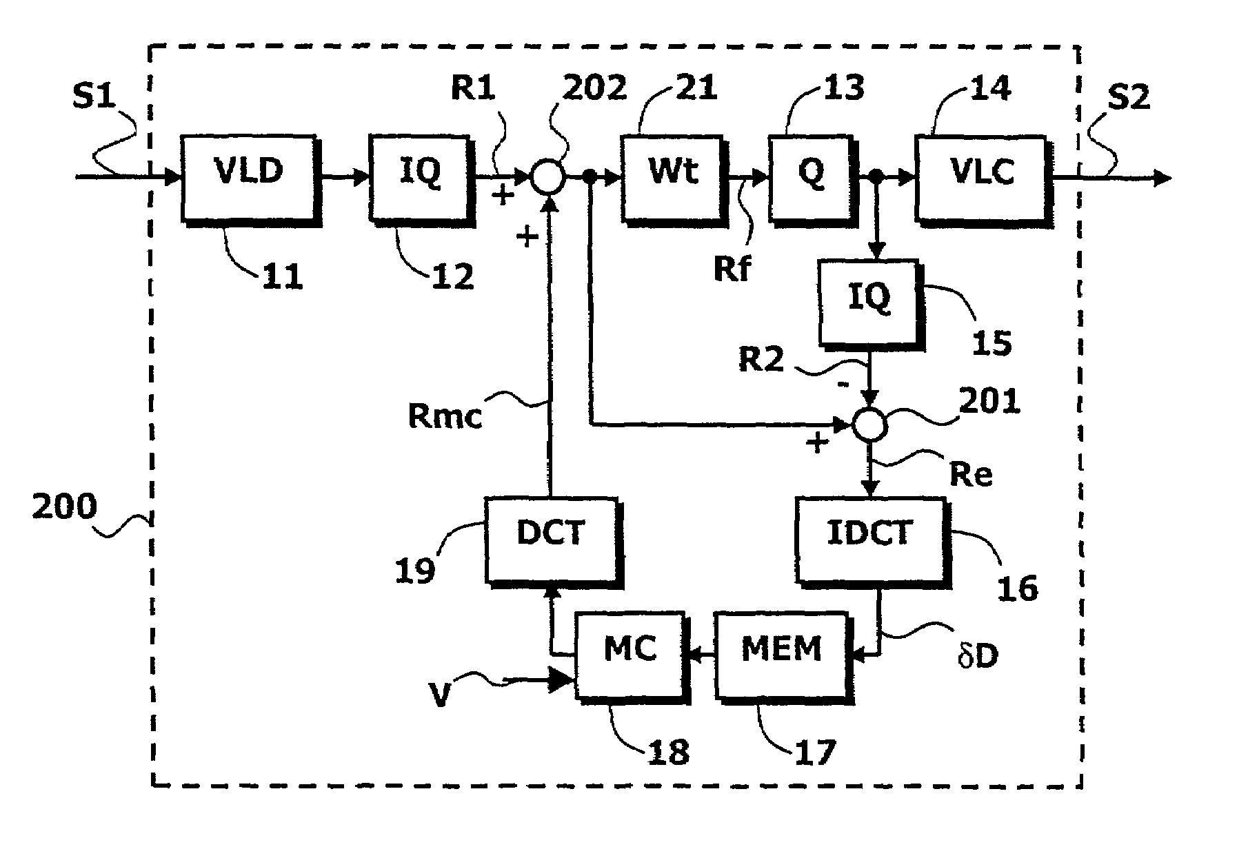
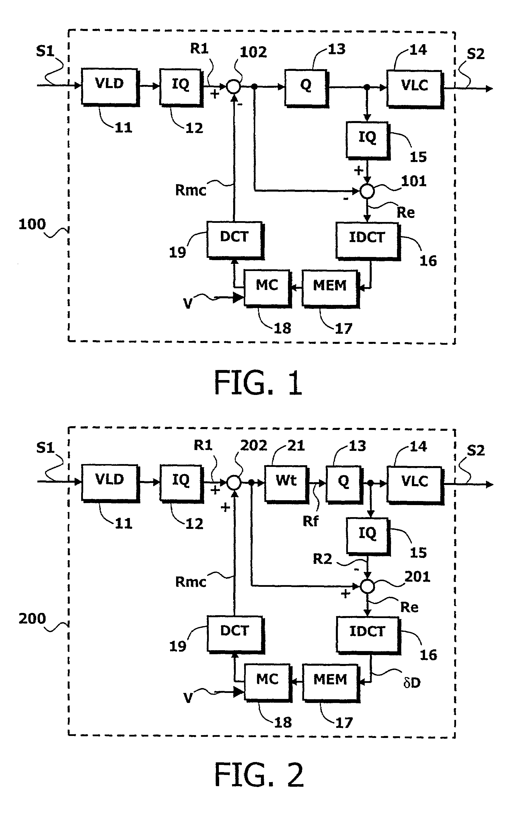
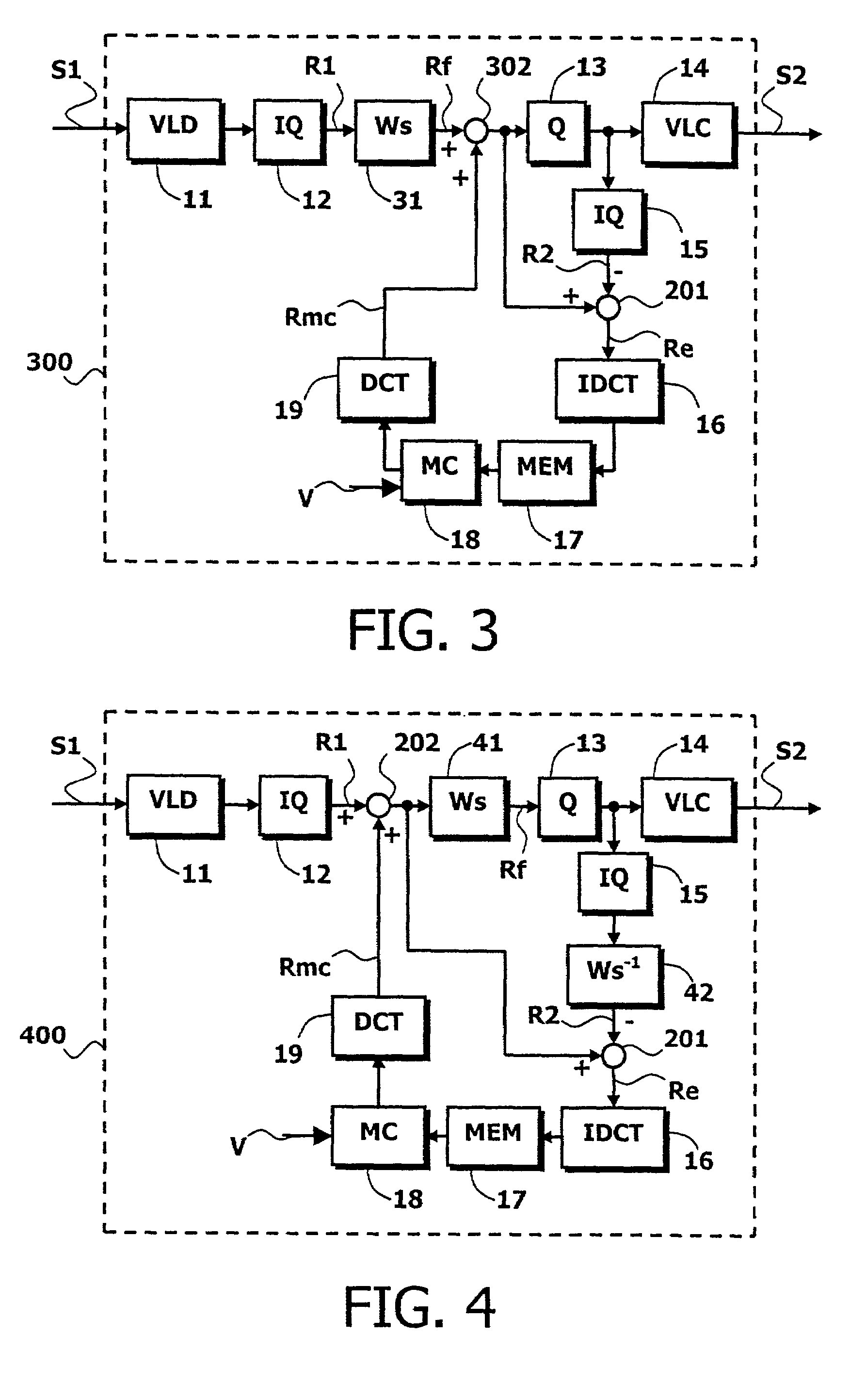
[0084]FIG. 3 shows a transcoder with spatial pre-filtering according to the invention. Said transcoder (300) comprises:[0085]a decoding channel, comprising a variable length decoder VLD (11) and a first dequantizer IQ (12) for producing a first transformed signal (R1),[0086]a spatial filter circuit Ws (31), for receiving said first transformed signal and for producing the filtered transformed signal (Rf),[0087]an encoding channel, comprising a quantizer Q (13), a variable length encoder VLC (14) and a second dequantizer IQ (15) for producing a second transformed signal (R2),[0088]a prediction channel, comprising in series:[0089]a subtractor (201), for determining a transformed encoding error (Re) and whose negative input receives the second transformed signal,[0090]an inverse discrete cosine transform circuit IDCT (16),[0091]a picture memory MEM (17),[0092]a circuit for motion-compensation MC (18),[0093]a discrete cosine transform circuit DCT (19) for predicting a transformed motion...
third embodiment
[0095]FIG. 4 is a transcoder according to the invention, with spatial post-filtering whose weight factors are Wsi,j. Said transcoder (400) comprises:[0096]a decoding channel, comprising a variable length decoder VLD (11) and a first dequantizer IQ (12) for producing a first transformed signal (R1),[0097]an encoding channel, comprising a quantizer Q (13), a variable length encoder VLC (14) and a second dequantizer IQ (15), and further comprising an inverse filter circuit (42) for producing a second transformed signal (R2),[0098]a prediction channel, comprising in series:[0099]a subtractor (201), for determining a transformed encoding error (Re) and whose negative input receives the second transformed signal,[0100]an inverse discrete cosine transform circuit IDCT (16),[0101]a picture memory MEM (17),[0102]a circuit for motion-compensation MC (18),[0103]a discrete cosine transform circuit DCT (19), for predicting a transformed motion-compensated signal (Rmc),[0104]an adder (202), for d...
PUM
 Abstract
Description
Claims
Application Information
 - R&D Engineer
- R&D Manager
- IP Professional
- Industry Leading Data Capabilities
- Powerful AI technology
- Patent DNA Extraction
Browse by: Latest US Patents, China's latest patents, Technical Efficacy Thesaurus, Application Domain, Technology Topic.
© 2024 PatSnap. All rights reserved.Legal|Privacy policy|Modern Slavery Act Transparency Statement|Sitemap