Measuring device using multi-start threaded spindle

a technology of threaded spindles and measuring devices, which is applied in the direction of measuring devices, mechanical measuring arrangements, instruments, etc., can solve the problems of reduced spindle strength, impaired precision of thread machination, and cumbersome measurement, so as to improve the measurement accuracy of the measuring device, reduce friction, and reduce the friction

Inactive Publication Date: 2006-03-21
MITUTOYO CORP
View PDF28 Cites 14 Cited by
  • Summary
  • Abstract
  • Description
  • Claims
  • Application Information

AI Technical Summary

Benefits of technology

[0011]The main object of the present invention is to resolve the problems inherent to conventional measuring devices by providing a measuring device enabling one to concurrently achieve high precision measurement and high-speed displacement of a spindle.

Problems solved by technology

With a measuring device whose spindle has a male thread with a pitch of 0.5 or 0.635 mm, however, measurement becomes very cumbersome if the measuring device must measure many objects different in size successively, because then the spindle must travel a considerable distance each time one object is exchanged for another, and the spindle must be revolved many times to cover the distance because of its single turn axial displacement being small.
This will in turn lead to the reduced strength of the spindle.
Such a spindle is prone to bend during preparation, and thus may cause the precise machination of threads to be impaired.
Moreover, if the thread of a spindle is made to have a large pitch while other things being kept invariable, the number of male threads on the spindle to engage with the female threads on a body will be reduced, which may reduce the resistance of the threads against a force applied on the axis of the spindle, and thus may cause the precision of axial displacement of the spindle to be impaired.
This problem may be circumvented by increasing the length of the male and female threads such that the number of male threads to engage with the female threads remains invariable.
However, such countermeasure will cause the overall size of the measuring device to be increased.

Method used


Image

  • Measuring device using multi-start threaded spindle
  • Measuring device using multi-start threaded spindle
  • Measuring device using multi-start threaded spindle

Examples


Embodiment Construction

)

[0033]An embodiment of the present invention will be described below with reference to attached figures.

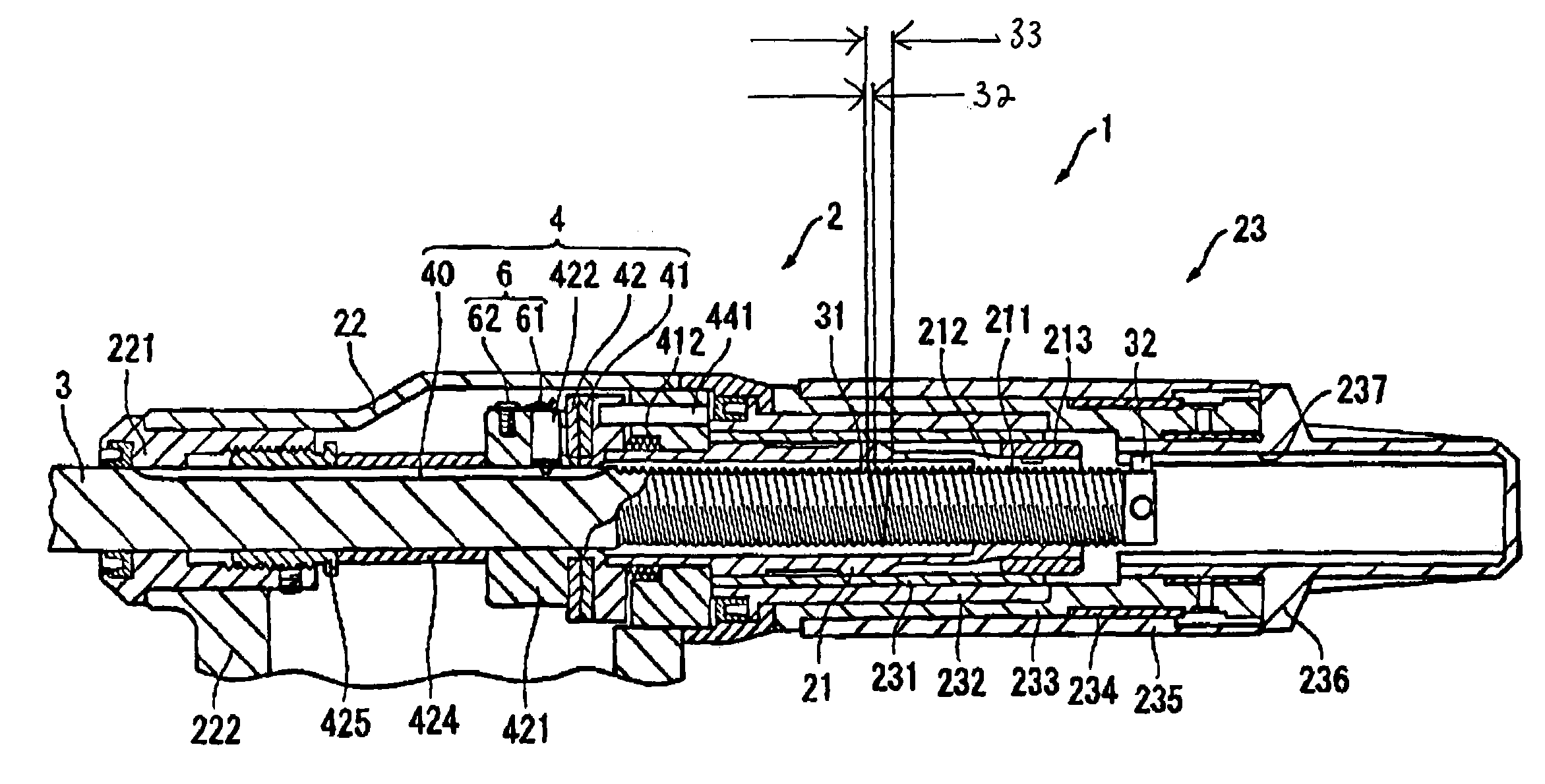
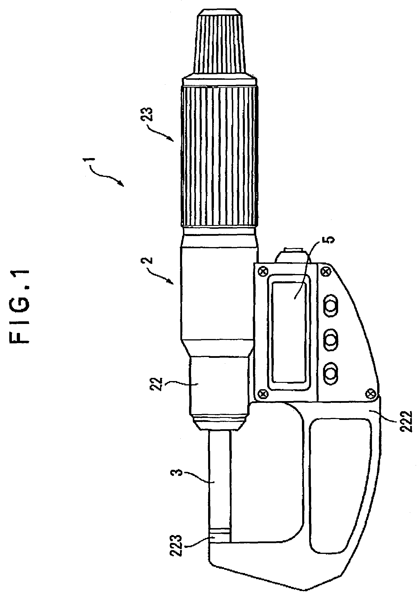
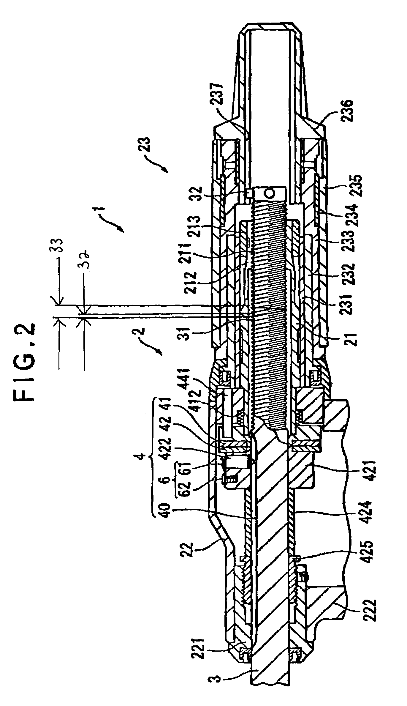
[0034]FIG. 1 shows a micrometer representing a first embodiment of the present invention. FIG. 2 is a sectional view of said embodiment.

[0035]The micrometer 1 comprises a body 2 having a U-shaped frame 222 with an anvil 223 on its one end, a spindle 3 which is screwed into an end of the body 2 so as to axially move by screwing towards or away from the anvil 223, a detection means 4 for detecting the axial displacement of the spindle 3 based on the revolution of the spindle 3, and a digital display portion 5 for displaying a measurement based on a signal from the detection means 4.

[0036]The body 2 comprises, from its distal end in order, a distal cylinder 22, a proximal cylinder 21, and a spindle driving portion 23.

[0037]The distal cylinder 22 comprises a stem 221 attached to the mouth of its distal end, and a U-shaped frame 222 attached to its outside. The U-shaped frame 222 has,...


PUM


Abstract

Provided is a measuring device 1 for measuring the size of an object comprising a body 2, and a spindle 3 which is screwed into the body 2 and axially advances and retracts by screwing with respect to the body 2, the measurement being based on the axial displacement of the spindle 3 effected by the revolution of the spindle, wherein the spindle is screwed into the body 2 via a multiple-start thread 31. Therefore, it is possible to displace the spindle 3 at a high speed, which improves the operability of the measuring device.

Description

BACKGROUND OF THE INVENTION[0001]1. Field of the Invention[0002]The present invention relates to a measuring device for measuring the size of an object by advancing or retracting a spindle by screwing with respect to the object, that is, a measuring device represented, for example, by micrometers and micrometer heads.[0003]2. Description of Related Art[0004]A conventionally known measuring device represented, for example, by micrometers and micrometer heads consists of a body with a female thread and a spindle with a male thread, the female and male threads engaging with each other, and measures the size of an object by advancing or retracting the spindle with respect to the object via screwing dependent on the engagement of the two threads.[0005]With such a measuring device, the axial displacement for each revolution of the spindle (single turn axial displacement) is determined by the pitch of male threads inscribed on the spindle.[0006]The male threads on the spindle of a conventi...

Claims


Application Information

Patent Timeline
Patent Type & Authority Patents(United States)
IPC IPC(8): G01B3/18
CPCG01B3/18
Inventor HAYASHIDA, SHUUJISASAKI, KOUJIICHIKAWA, YUICHISAITO, OSAMUTAKAHASHI, SEIGOSUZUKI, MASAMICHINAKADOI, TETSUYATACHIKAKE, MASAHIKONAKAMURA, TAKAHIROOKAMOTO, MASAFUMIHASHIMOTO, YUUZOU
Owner MITUTOYO CORP
Why Eureka
Try Eureka