Apparatus for handling tubulars and method

a technology for tubulars and apparatuses, applied in mechanical apparatuses, manufacturing tools, gearing, etc., can solve the problems of affecting etc., to achieve the effect of increasing the accuracy of jaws

Active Publication Date: 2006-03-21
FORUM US
View PDF6 Cites 36 Cited by
  • Summary
  • Abstract
  • Description
  • Claims
  • Application Information

AI Technical Summary

Benefits of technology

[0011]An advantage of the present invention is a gear-driven gripping method will be implemented in order to increase the accuracy of jaws between the upper and lower assembly. The gear-driven gripping method will eliminate the need for the operator to change jaws due to a change in tool size. Another advantage is that the jaw system will contain three jaws per tool that will be drawn together uniformly via gearing in order to ensure centering of the tubular consistently.
[0012]Yet another advantage is that the action as well as the geometry of the tool and jaws allows for equal velocity between the three (3) jaws as they approach the center of rotation. Another advantage is that the equiangular geometry of the jaw channels allows for constant equiangular geometry of the jaws themselves. This equiangular contact between the jaw face and the surface of the tubular creates equal forces at three points all equidistant from each other. Still yet another advantage is that the equal velocity paired with the geometry of the jaw travel allows for centering of the tubular with the center of rotation of the tool repeatable constantly.
[0013]A feature of the present invention is that each assembly will implement a single gripping cylinder used in the actuation of all three (3) jaws. Another feature is that the four (4) gears and racks will be used per assembly. Yet another feature is that two (2) torque cylinders will be used between the required two (2) assemblies per torque tool. Another feature is that the two (2) torque cylinders being used in series will allow for torques to be created that meet and / or exceed the requirements for this tool during operation. Still yet another feature is that the upper and lower assemblies are interchangeable in the preferred embodiment. Another feature includes the use of hydraulic or electronic remote control of the activation means.

Problems solved by technology

Many problems have been experienced with prior art torque tools.
Prior art tools have experienced significant problems with proper alignment.
Hence, the jaws of the torque tools would have to be replaced, which is a time consuming and expensive operation due to high day rates charged by rigs.

Method used


Image

  • Apparatus for handling tubulars and method
  • Apparatus for handling tubulars and method
  • Apparatus for handling tubulars and method

Examples


Embodiment Construction

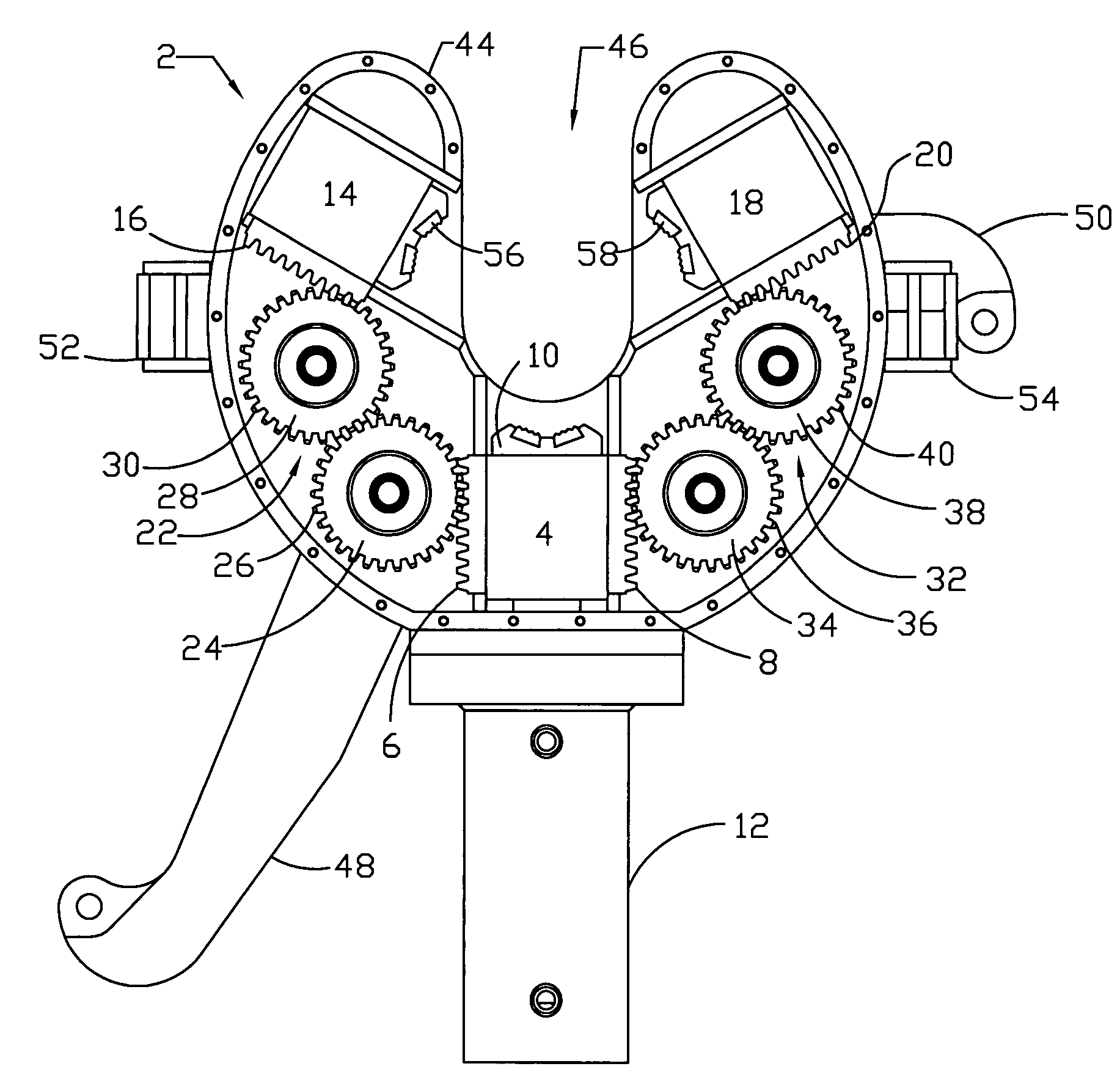
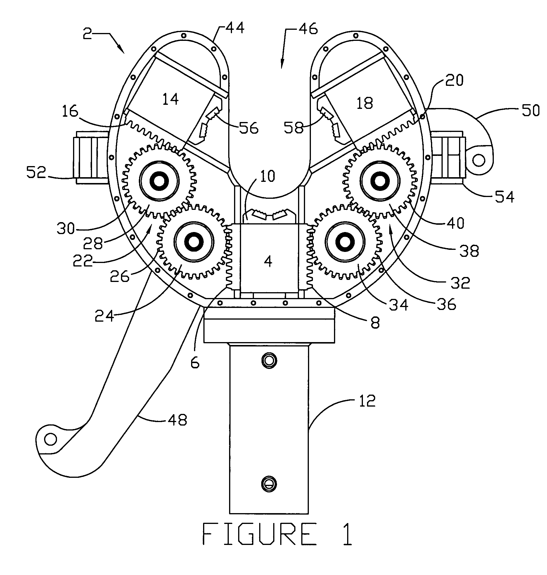
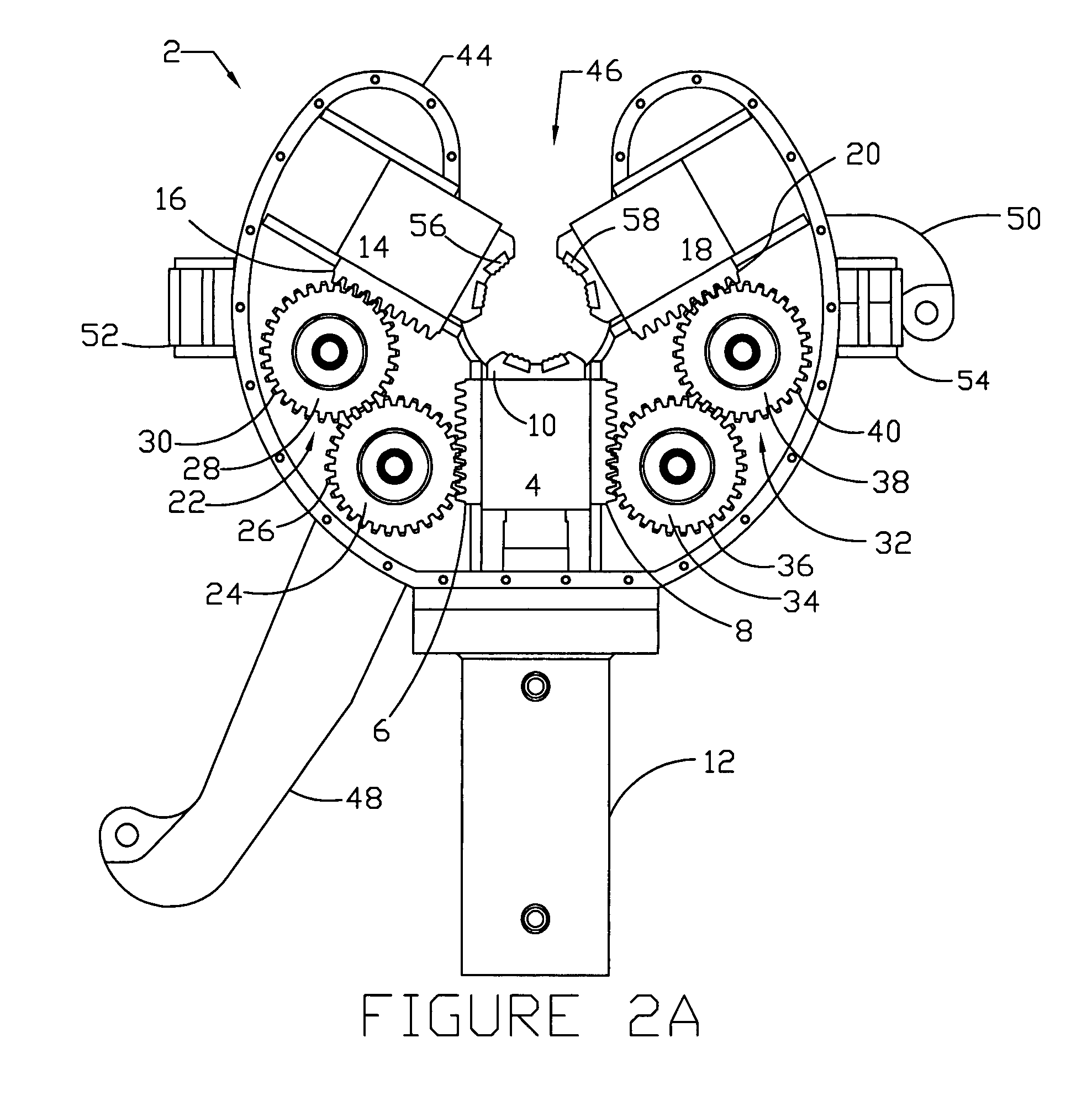
[0022]Referring now to FIG. 1, a partial cross-sectional view of the preferred embodiment of the self-centering apparatus 2 with the jaws in the expanded position will now be described. In this preferred embodiment, the driving jaw device 4 is shown having a rack device, and in particular, the first rack 6 and the second rack 8. The driving jaw device 4 further includes the jaw die inserts 10, and wherein the jaw die inserts 10 will engage the tubular as will be more fully described later in the application. FIG. 1 shows the hydraulic cylinder 12 which is operatively attached to the driving jaw device 4. The hydraulic cylinder 12 acts as the driving cylinder for the driving jaw device 4.

[0023]FIG. 1 further depicts the first driven jaw 14 that will have the third rack 16, as well the second driven jaw 18 that contains the fourth rack 20. The self-centering apparatus 2 will contain the first gear means 22 that contains the primary idler gear 24 with associated teeth 26 and the second...


PUM


Abstract

A device for torquing a tubular connection. The device comprises an upper assembly having an upper jaw member, a lower assembly having a lower jaw member, an upper gear for advancing the upper jaw member, and a lower gear for advancing the lower jaw member. The upper jaw member includes a first jaw operatively associated with a first rack, a second jaw operatively associated with a second rack, and a third jaw operatively associated with a third rack. The lower jaw member includes a fourth jaw operatively associated with a fourth rack, a fifth jaw operatively associated with a fifth rack, and a sixth jaw operatively associated with a sixth rack. A method of torquing a first tubular with a second tubular is also disclosed.

Description

BACKGROUND OF THE INVENTION[0001]This invention relates to an apparatus for handling tubulars. More particularly, but not by way of limitation, this invention relates to an apparatus for centering tubular connections, applying torque to the tubular connections as well as breaking the tubular connection.[0002]In the course of drilling wells, operators will find it necessary to threadedly connect and disconnect tubular strings. For instance, tubulars that are run into well bores will be required to be made up on the rig floor. As readily appreciated by those of ordinary skill in the art, operators will use specialized tools in order to create the necessary torque required to properly connect the tubulars.[0003]Many problems have been experienced with prior art torque tools. For instance, in order to make up the box end to the pin end, the two tubulars must be properly aligned. Prior art tools have experienced significant problems with proper alignment. Also as appreciated by those of ...

Claims


Application Information

Patent Timeline
Patent Type & Authority Patents(United States)
IPC IPC(8): B25B17/00B25B13/50B25B29/00
CPCE21B19/163Y10T74/1967Y10T74/18808
Inventor CHILDRESS, II, LAWRENCE E.
Owner FORUM US
Why Eureka
Try Eureka