
Sliding globe assembly for lantern

a technology for lanterns and globes, applied in the field of lanterns, can solve the problems of difficult access to mantles for installing or replacing one or more mantles, difficult to cool down these components, and the mantles for lanterns are often very bright, so as to achieve the effect of minimizing glar

Inactive Publication Date: 2006-03-21
THE COLEMAN CO INC
View PDF12 Cites 11 Cited by
  • Summary
  • Abstract
  • Description
  • Claims
  • Application Information

AI Technical Summary

Benefits of technology

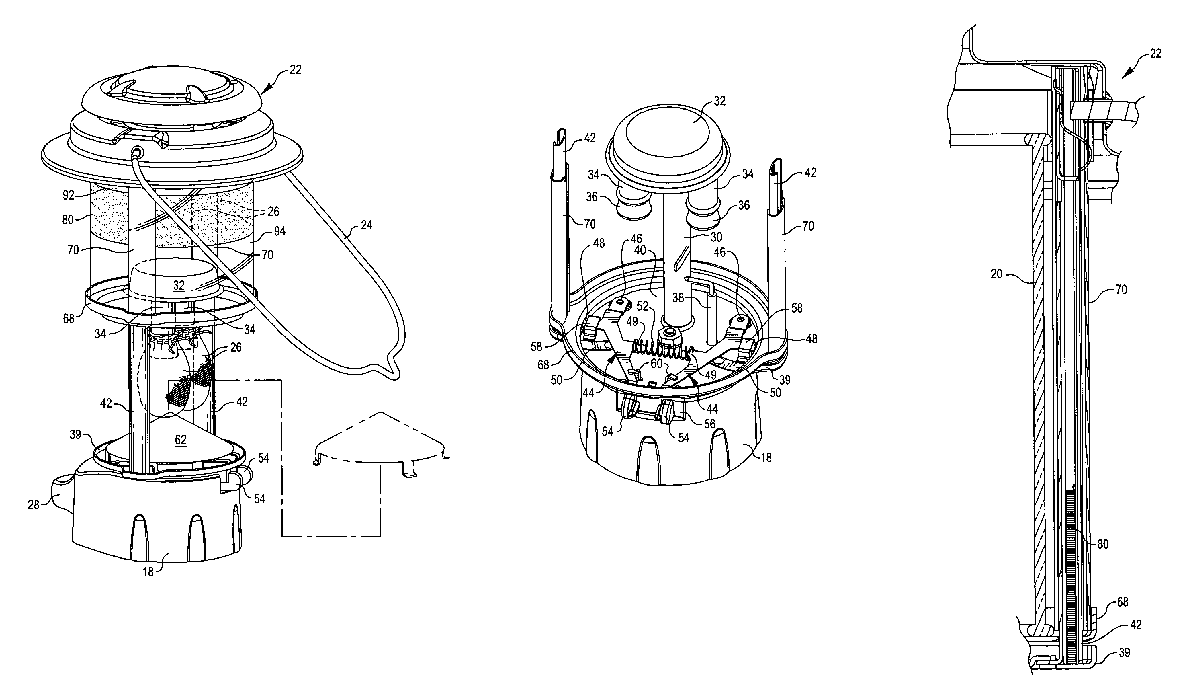
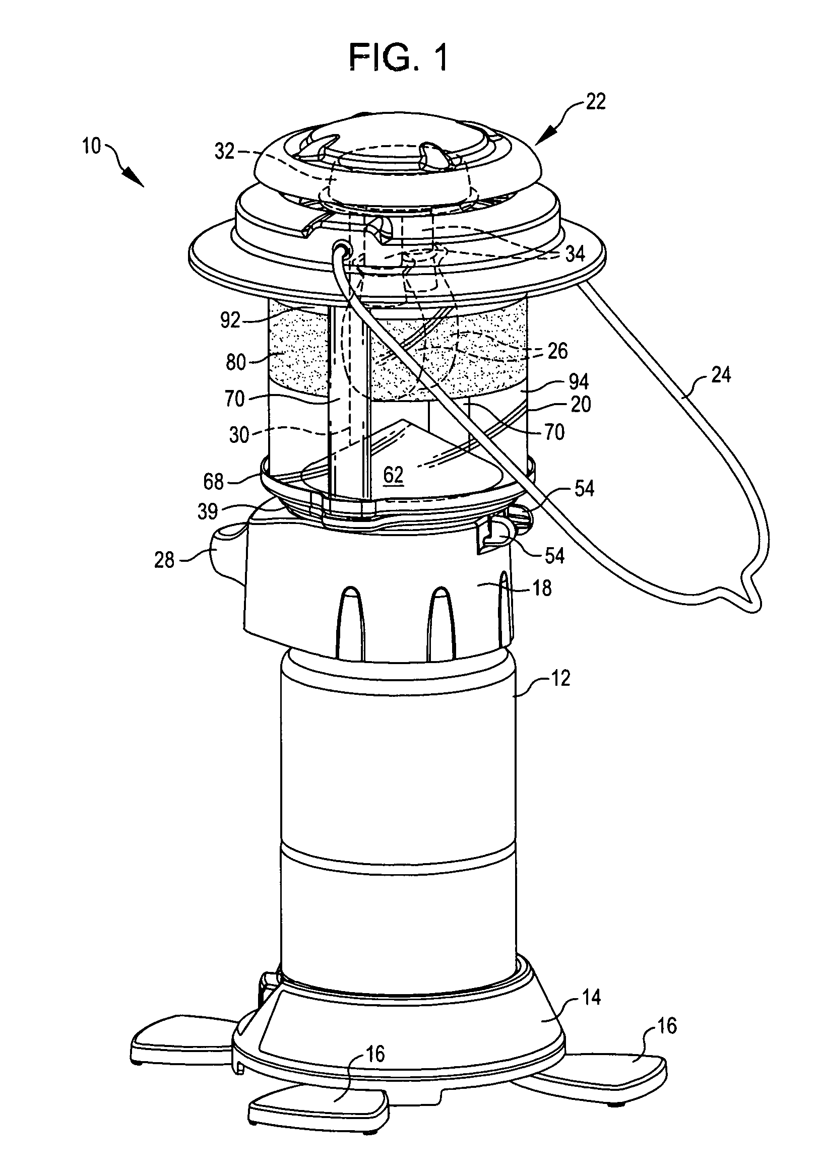
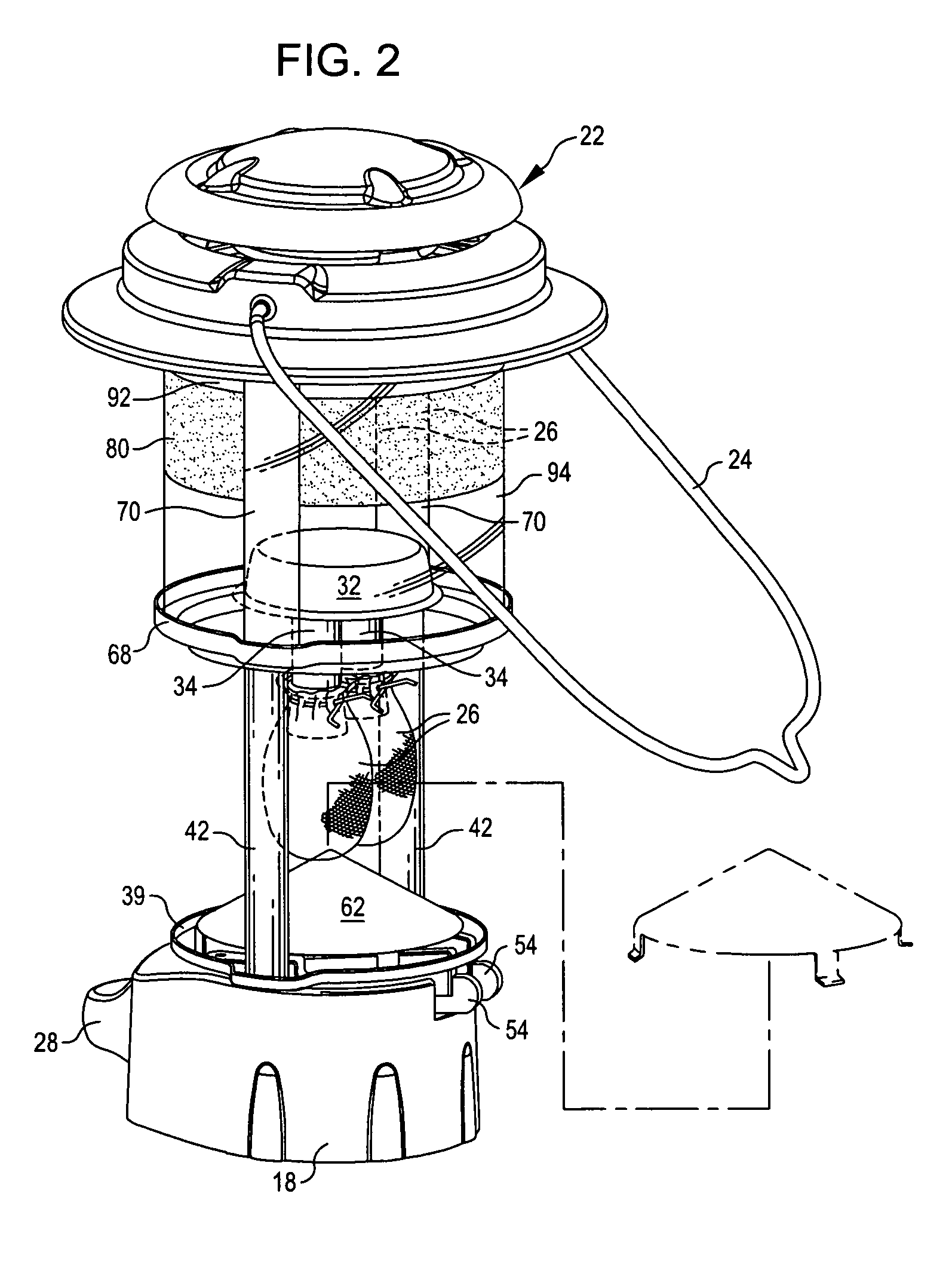
[0008]Because the lantern of the present invention provides translation of the globe relative to the mantles, instead of removal of the globe, the lantern of the present invention does not have to be disassembled for replacement or installation of the mantles. In addition, in accordance with one aspect of the present invention, the lantern is easily manipulated by a user with limited dexterity, such as a user with arthritis. In accordance with another aspect, a user may translate the globe relative to the mantle by using a single hand.
[0011]In accordance with another aspect of the present invention, a mechanism is provided that supplies friction against the translated movement of the globe relative to the mantles. The friction mechanism permits movement of the globe relative to the mantles to be stopped at any point, without the globe automatically returning by gravity to the closed position. As an example, a leaf spring may be provided that engages rails upon which the globe is mounted and resists sliding of the rails relative to the mantles.
[0012]In accordance with another aspect of the present invention, a globe for the lantern includes a frosted band located on a circumference of the globe radially outward from the mantle or mantles. The frosted band minimizes glare from the lantern, and the combination of the frosted band and clear sections located above and below the band provide illumination substantially equal to a clear globe, without the associated glare.

Problems solved by technology

One problem encountered with prior art lanterns is that the mantles are difficult to access for installing or replacement of one or more mantles.
In addition, because handling of the globe and ventilator cap assembly is required, a user must wait for these items to cool before removing.
Waiting for these components to cool may take some time.
Another problem with prior art lanterns is that the mantles for the lanterns often are very bright, especially when viewed through a clear globe.
However, it has been found that these completely frosted globes block a large amount of light produced by a lantern, and thus significantly reduce the illumination provided by the lantern.

Method used


Image

  • Sliding globe assembly for lantern
  • Sliding globe assembly for lantern
  • Sliding globe assembly for lantern

Examples


Embodiment Construction

[0024]In the following description, various aspects of the present invention will be described. For purposes of explanation, specific configurations and details are set forth in order to provide a thorough understanding of the present invention. However, it will also be apparent to one skilled in the art that the present invention may be practiced without the specific details. Furthermore, well-known features may be omitted or simplified in order not to obscure the present invention. In addition, to the extent that orientations of the invention are described, such as “top,”“bottom,”“front,”“rear,” and the like, the orientations are to aid the reader in understanding the invention, and are not meant to be limiting.

[0025]Referring now to the drawings, in which like reference numerals represent like parts throughout the several views, FIG. 1 shows a lantern 10 incorporating the present invention. In the embodiment shown in FIG. 1, the lantern 10 includes a propane tank 12. However, the...


PUM


Abstract

A lantern which may be manipulated between a closed position in which it surrounds a mantle or mantles for the lantern to a second, opened position in which the globe has been moved or otherwise manipulated to provide access to the mantle or mantles. As an example, the globe may slide upward relative to the mantles so as to expose the mantles for changing. A globe for the lantern includes a frosted band located on a circumference radially outward from the mantle or mantles. The frosted band minimizes glare from the lantern, and the combination of the frosted band and clear sections located above and below the band provide illumination substantially equal to a clear globe.

Description

TECHNICAL FIELD OF THE INVENTION[0001]The present invention relates to lanterns, and more particularly, to installation or replacement of a mantle in a lantern.BACKGROUND OF THE INVENTION[0002]Lanterns that burn liquid fuel or LP fuel are well known. Such lanterns include a burner assembly to which the fuel is delivered and one or more catalytic mantles which are mounted on the burner assembly. The fuel burns within the catalytic mantles and the mantles incandesce and provide a bright light. The mantles are usually surrounded by a glass cylindrical globe.[0003]Mantles are generally formed from mesh material, and are shaped like a small bag with one open end. The open end is secured around the outlet end of a burner tube of the burner assembly of a lantern. The mantle may be attached, for example, by a drawstring. Alternatively, the mantle may be attached by a spring clip, such as is shown in U.S. Pat. No. 5,639,231.[0004]One problem encountered with prior art lanterns is that the ma...

Claims


Application Information

Patent Timeline
Patent Type & Authority Patents(United States)
IPC IPC(8): F21H1/00F21V3/00F21V17/00F21V17/18F21V36/00
CPCF21H1/00F21V36/00F21V3/00F21L19/003
Inventor LONG, NORRIS RICHARD
Owner THE COLEMAN CO INC
Learn More