Method for manufacturing an optical pickup

Inactive Publication Date: 2006-03-21
PANASONIC CORP
View PDF12 Cites 2 Cited by
  • Summary
  • Abstract
  • Description
  • Claims
  • Application Information

AI Technical Summary

Benefits of technology

[0016]The present invention aims to provide an optical pickup manufacturing method that enables a pair of elastic support member groups, which are each made up of three or more elastic support members arranged in parallel in the focusing direction, to be connected to the movable member and the fixed member by insert molding (i.e., to be inserted in the movable member and the fixed member).

Problems solved by technology

When solder is used, however, the influence of heat generated from the molten solder extends to the connecting parts, which tends to cause the movable member or the fixed member to become thermally deformed.
Hence it is difficult to ensure the precise connection positions of the elastic support members.
When an adhesive is used, on the other hand, the shrinkage of the adhesive as a result of hardening is relatively high, which tends to cause the elastic support members to be displaced.
According to the above manufacturing method, however, it is not practical to add more elastic support members in the focusing direction.
However, this requires an extremely complex mold structure, and causes a significant drop in productivity.
Hence the above manufacturing method cannot be employed in this case.
This, however, causes an increase in size of the entire optical pickup.

Method used


Image

  • Method for manufacturing an optical pickup
  • Method for manufacturing an optical pickup
  • Method for manufacturing an optical pickup

Examples


first embodiment

(First Embodiment)

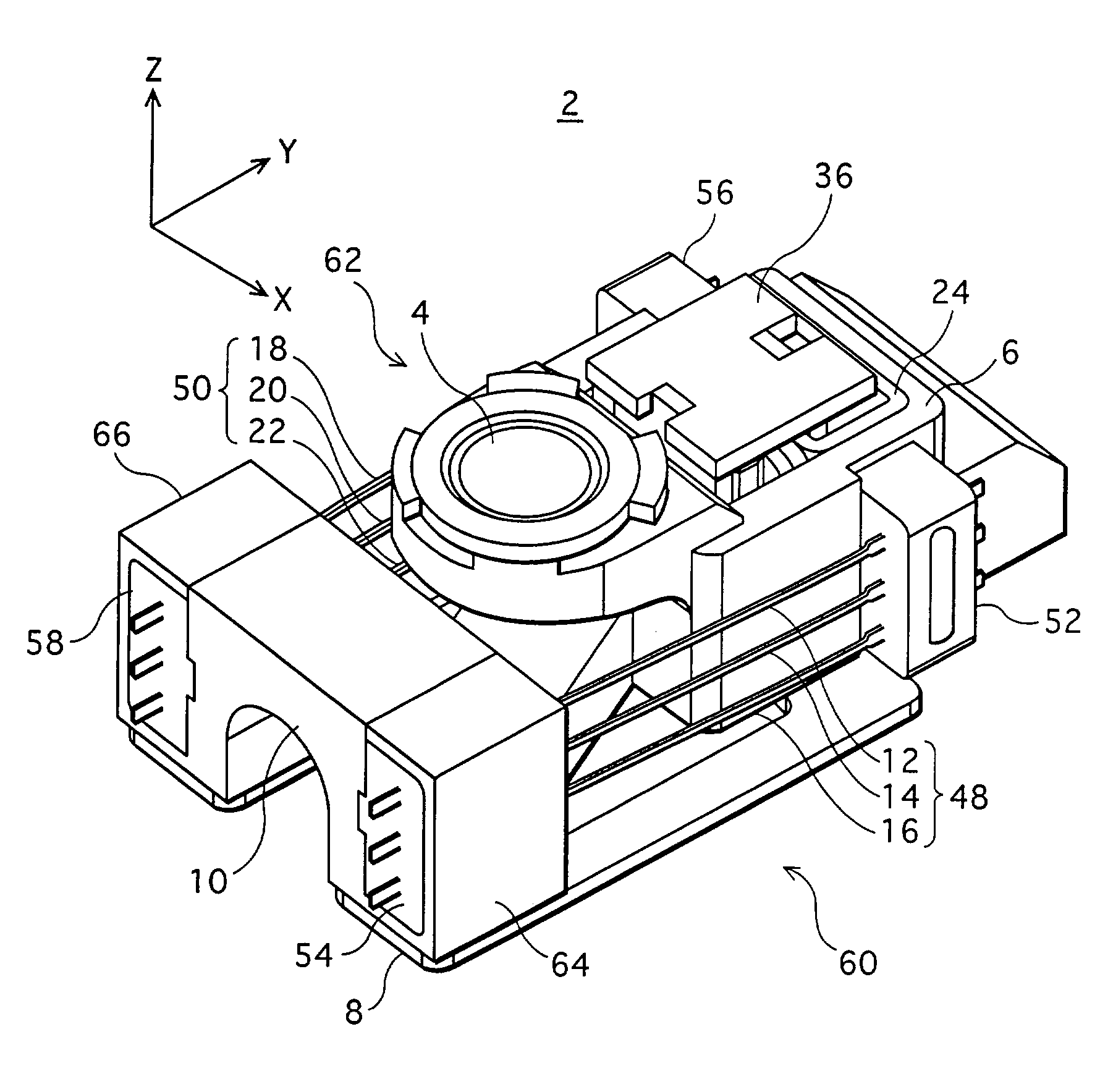
[0045]FIG. 3 is a perspective view showing a rough construction of an optical pickup 2 to which the first embodiment of the invention relates. FIG. 4 is a top view of the optical pickup 2, whereas FIG. 5 is an exploded perspective view of the optical pickup 2. Note that an auxiliary yoke 36 shown in FIG. 3 has been omitted in FIG. 4.

[0046]In this specification, a focusing direction denotes a direction of an optical axis of an objective lens, whereas a tracking direction denotes a direction intersecting a track of an optical recording medium (e.g. CD or DVD) which is subjected to recording / playback. In an XYZ orthogonal coordinate system in FIG. 3, the Z direction is the focusing direction and the X direction is the tracking direction.

[0047]The optical pickup 2 has an enclosure 6 which is movable and a block 10 which is fixed. The enclosure 6 is made of a resin, and carries optical components such as an objective lens 4 and a liquid crystal tilt correction component...

second embodiment

(Second Embodiment)

[0109]The second embodiment of the present invention has basically the same construction as the first embodiment, and differs only in the construction of a suspension unit. Accordingly, the following description focuses on the suspension unit, while omitting the same features as those of the first embodiment.

[0110]FIG. 17A is a perspective view showing a rough construction of an optical pickup 102 to which the second embodiment relates. FIG. 17B is a side view of the optical pickup 102 as seen in the tracking direction. FIG. 17C is a top view of the optical pickup 102 as seen in the focusing direction. Note that the auxiliary yoke, the gel retention members, and the vibration suppression members made of a gel are omitted in these drawings.

[0111]In this embodiment, each of a pair of suspension units 104 and 106 has the following construction, as shown in FIG. 17. In the suspension unit 104, the ends of three elastic support members 108, 110, and 112 connected to ho...

third embodiment

(Third Embodiment)

[0120]In the third embodiment of the present invention, more electrical / electronic components are mounted on the enclosure (movable member) than in the first embodiment. Accordingly, more elastic support members are provided to respond to the need for more wires.

[0121]FIG. 18 is a perspective view of an optical pickup 302 to which the third embodiment relates. FIG. 19 is an exploded perspective view of the optical pickup 302. Note that auxiliary yokes 356R and 356L shown in FIG. 19 are omitted in FIG. 18.

[0122]This optical pickup 302 is a so-called optical-component-integrated optical pickup. Which is to say, the optical pickup 302 has an enclosure 306 which is movable and a block 310 which is fixed. The enclosure 306 is made of a resin, and carries all optical components of an optical system including a semiconductor laser and an objective lens 304 (FIG. 20). The block 310 is equally made of the resin, and is fixed onto a base 308. The enclosure 306 and the block ...


PUM

PropertyMeasurementUnit
Elasticityaaaaaaaaaa
Symmetryaaaaaaaaaa

Abstract

To provide a manufacturing method for an optical pickup in which a movable member carrying an objective lens is supported by a fixed member through a pair of elastic support member groups, which are each made up of a plurality of parallel elastic support members, so as to be movable in focusing and tracking directions. In a suspension unit forming step, two holding members are formed from a synthetic resin by insert molding at different positions of each elastic support member group in a lengthwise direction of the elastic support members, thereby forming a pair of suspension units. In a connecting step, the pair of suspension units are opposed with an arrangement direction of the elastic support members being substantially the same as the focusing direction, and one holding member of each suspension unit is connected to the movable member and the other holding member to the fixed member.

Description

[0001]This application is based on an application No. 2002-101871 filed in Japan, the contents of which are hereby incorporated by reference.BACKGROUND OF THE INVENTION[0002]1. Field of the Invention[0003]The present invention relates to a method for manufacturing an optical pickup. The invention in particular relates to a manufacturing method for an optical pickup in which a movable member carrying an objective lens is movably supported by a fixed member through a plurality of elastic support members.[0004]2. Prior Art[0005]An optical pickup is used to read information from (i.e. playback) or write information onto (i.e. recording) an optical recording medium such as a CD (compact disc) or a DVD (digital versatile disc). Such an optical pickup is expected to record / play information reliably without being affected by the wobble of the information recording surface or track of the optical recording medium. For this purpose, the optical pickup needs to have a mechanism of moving an ob...

Claims


Application Information

Patent Timeline
IPC IPC(8): B29D11/00B29C45/00B29C45/14G11B7/09G11B7/22
CPCG11B7/22G11B7/0932B29C45/14467B29C45/0053G11B7/08
Inventor IJIMA, SHINICHIISHIDO, TERUKIYAMANAKA, KAZUHIKOONOZAWA, KAZUTOSHI
Owner PANASONIC CORP
Why Eureka
Try Eureka