Process for treatment of organic waste materials

a technology for processing waste materials and organic waste, which is applied in the field of processing waste materials, can solve the problems of high energy consumption during material processing, runoff from the composting facility, and emissions of noxious gases, and achieves the effects of reducing the net energy requirement associated, rapid and inexpensive process scaling, and reducing emissions

Inactive Publication Date: 2006-03-21
RECOLOGY ENVIRONMENTAL SOLUTIONS INC
View PDF14 Cites 30 Cited by
  • Summary
  • Abstract
  • Description
  • Claims
  • Application Information

AI Technical Summary

Benefits of technology

[0008]The liquid hydrolysis product transferred from the vessel, which may be temporarily stored in a holding tank, is passed to a conventional anaerobic digester. In a thermophilic digester, methanogenic bacteria convert organic matter that is dissolved and / or suspended in the liquid hydrolysis product to a biogas product. The biogas product may be combusted prior to release to the atmosphere in order to eliminate or reduce emissions of flammable or otherwise objectionable gaseous species, such as methane. Thermal energy produced by combustion of the biogas may be utilized to supply heat and / or electrical power for processing operations. The liquid digester product remaining after completion of the digestion process may be removed from the digester and employed as inoculant for hydrolysis of subsequently processed organic waste material.
[0010]The foregoing waste material treatment process present several advantages over prior art techniques, including the reduction of emissions of ozone precursors and other noxious or otherwise objectionable gases (by removal of such species during the hydrolysis process), lowering the net energy requirements associated with the composting process (since energy required for material processing is offset by energy produced by utilization of the biogas product), and the ability to rapidly and inexpensively scale the process to meet peak throughput demands by adjusting the number and capacity of the relatively low-cost hydrolysis vessels.

Problems solved by technology

The growing use of composting as a preferred alternative to disposal of organic waste material has made some common environmental problems apparent.
These problems include emissions of noxious gases and ozone pre-cursors, runoff from the compost facility, and high energy consumption during material processing.
These problems may become particularly acute if the organic waste material contains large amounts of food waste or other high moisture content waste.

Method used


Image

  • Process for treatment of organic waste materials
  • Process for treatment of organic waste materials
  • Process for treatment of organic waste materials

Examples


Embodiment Construction

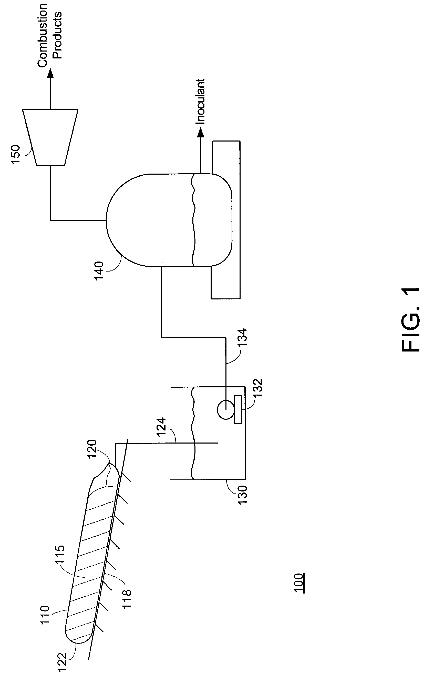
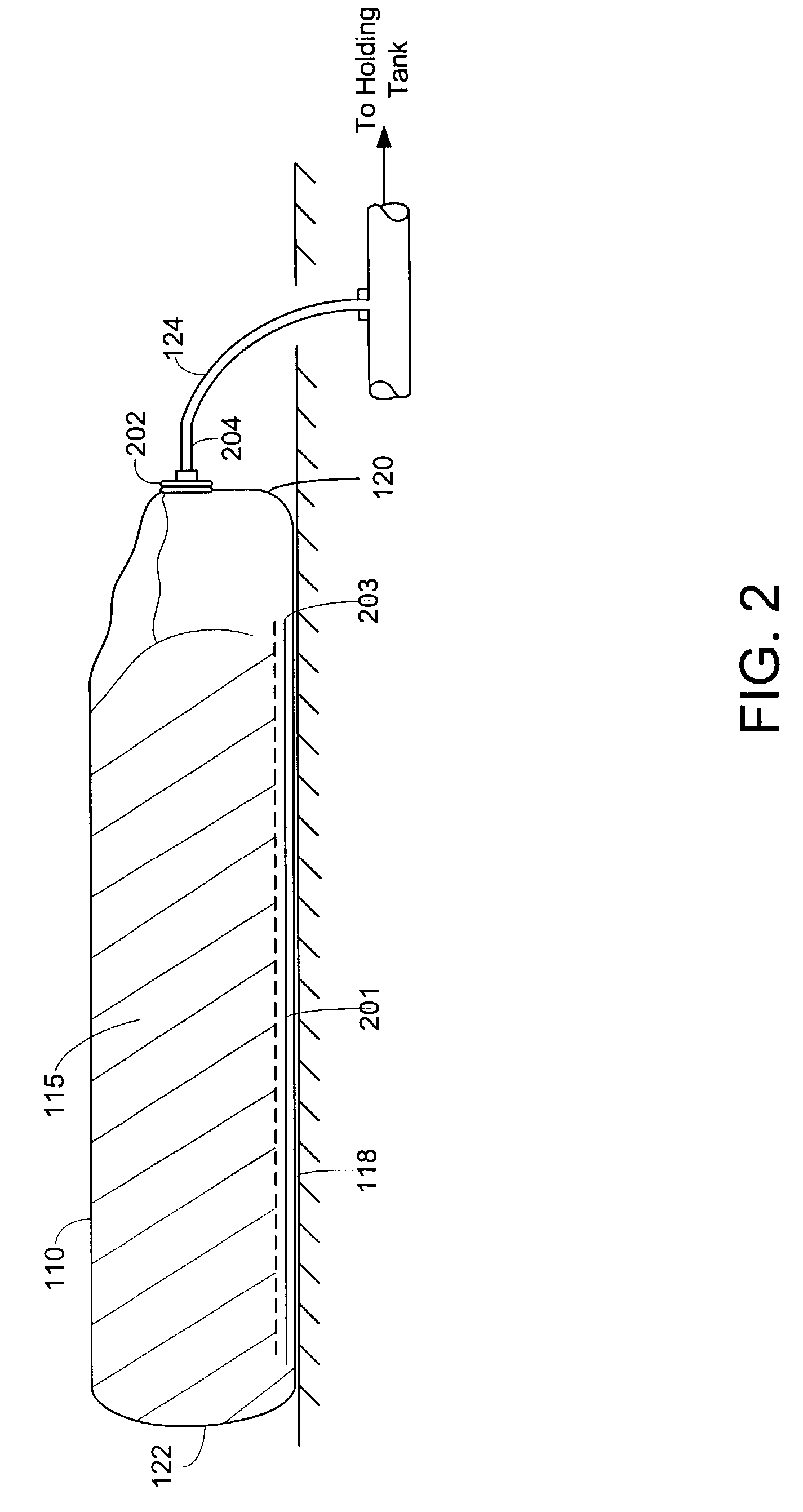
[0016]FIG. 1 symbolically depicts the major components of an organic waste treatment system 100 implemented in accordance with an exemplary embodiment of the invention. A flexible hydrolysis vessel 110 contains a volume of organic waste material 115 having relatively high moisture content and density. The hydrolysis vessel 110 has pliable walls formed from a polymer or other material that is substantially impermeable to gases and liquids. The ends of vessel 110 are closed and sealed to provide an anaerobic environment for the hydrolysis of the organic waste material 115. Details regarding the construction of vessel 100 are set forth below in connection with FIG. 2.

[0017]The vessel 100 rests on a supporting surface 118, which is sloped along the longitudinal axis of vessel 110 such that the bottom portion of a first end 120 of the vessel 110 is situated lower than the bottom portion of the opposite end 122 of the vessel 110. This condition causes liquids produced during anaerobic hyd...


PUM

PropertyMeasurementUnit
lengthaaaaaaaaaa
lengthaaaaaaaaaa
particle sizeaaaaaaaaaa

Abstract

A multi-stage process and system for treating organic waste materials includes steps of hydrolyzing the materials in an anaerobic vessel, transferring the liquid product of hydrolysis to an anaerobic digester, and further decomposing the waste materials under aerobic conditions to yield a compost product usable as a soil amendment. Biogas produced by digestion of the hydrolysis liquid product may be burned to generate electricity or heat, and the liquid digester product may be recirculated for use as an inoculant to aid hydrolysis of subsequently processed batches of waste materials.

Description

BACKGROUND[0001]1. Field of the Invention[0002]The present invention relates generally to processing of waste materials, and more particularly to processes and systems for treating organic waste materials to form a compost product.[0003]2. Description of the Prior Art[0004]Anaerobic digestion and composting processes have co-existed for many years as disposal alternatives for organic waste materials. Such materials include agricultural materials, “green” wastes, and pre- and post-consumer wastes. The primary objective of anaerobic digestion is the production of a mixture of hydrocarbon gases (“biogas”), which may be utilized as an energy source to generate electricity and / or heat. Any solid material remaining at the completion of the anaerobic digestion process is typically disposed of by conventional methods, such as transferring the material to a landfill. In contrast, composting processes focus on the production of a solid product that may be employed as a soil amendment.[0005]Be...

Claims


Application Information

Patent Timeline
Patent Type & Authority Patents(United States)
IPC IPC(8): B09B3/00B01D1/00C02F1/00C12M1/00C12M3/00C02F3/28C05F17/00C07G99/00C12N9/14C12P1/04
CPCC05F17/0027C02F3/286Y02E50/343C12M21/04C12M23/26C12M23/50C12M23/58C12M45/06C05F17/50Y02E50/30Y02W10/10Y02W30/40Y02P20/145
Inventor CHOATE, CHRIS E.SHERMAN, PAUL A.ZHANG, RUIHONG
Owner RECOLOGY ENVIRONMENTAL SOLUTIONS INC
Why Eureka
Try Eureka