Automatic document feeder and image forming apparatus including the same

a technology of automatic document feeder and image forming apparatus, which is applied in the direction of electrographic process, instruments, transportation and packaging, etc., can solve the problems of obstructing small size, increasing cost, and impurities including dust prone to enter the adf, so as to achieve space saving and easy removal

Inactive Publication Date: 2006-03-21
RICOH KK
View PDF12 Cites 19 Cited by
  • Summary
  • Abstract
  • Description
  • Claims
  • Application Information

AI Technical Summary

Benefits of technology

[0017]It is an object of the present invention to provide an ADF including a single receipt tray positioned below a feed tray and shared by the one-side mode and both-side mode for thereby promoting rapid conveyance, and an image forming apparatus including the same.
[0018]It is another object of the present invention to provide an ADF allowing a document jamming a discharge path to be easily removed, and an image forming apparatus Including the same.
[0019]It is a further object of the present invention to provide a simple, space saving ADF, and an image forming apparatus including the same.
[0020]an ADF of the present invention includes a feed tray configured to allow documents to be stacked thereon with front sides facing upward. A receipt tray is positioned below the feed tray, but above a scanning position, and configured to allow each document having one side or both sides scanned at the scanning position to be driven out to the receipt tray. The receipt tray is angularly movable such that its outlet side thereof opens. A feeding section sequentially feeds the top document to the bottom document stacked on the feed tray one by one while separating each document from the underlying documents. A first conveying section reverses the document fed by the feeding section and conveys it to the scanning position. A second conveying section conveys the document from the scanning position to a shared path available for both of the one-side scanning mode and both-side scanning mode, reverses the document, and again conveys the document to the scanning position. A switchback conveying section conveys the document reversed by the second conveying section via the shared path to a switchback path below the receipt tray. A guide is constructed integrally with the receipt tray for reversing the document driven out of the switchback path by the switchback conveying section in the reverse direction toward an outlet via the shared path. A third conveying section conveys the document conveyed from the scanning position toward the outlet via the shared path to the receipt tray. Switching members steer the document toward one of the shared path, the switchback path and a reversal path along which the document reversed after scanning is again brought to the scanning position. A cover covers part of the second conveying means, guide means and switching members to thereby delimit the shared path. The cover is angularly movable for uncovering the shared path. A controller causes the switching members to steer, in the both-side scanning mode, the document whose both sides have been scanned toward the shared path or to steer, in the one-side scanning mode, the document whose one side has been scanned toward the switchback path.

Problems solved by technology

However, the two receipt trays or the protruding feed tray occupies an extra space in addition to the space of the ADF itself.
Laid-Open publication No. 9-292742 has a problem that the path at the discharging side is sophisticated and needs a great number of parts, resulting in an increase in cost.
A problem with Laid-Open Publication No. 5-6053 is that when the movable main frame is opened for the removal of a jamming sheet, impurities including dust are apt to enter the ADF.
This obstructs small size, space saving construction.
Then, a top cover, for example, protrudes above the ADF and again obstructs small size, space saving construction.

Method used


Image

  • Automatic document feeder and image forming apparatus including the same
  • Automatic document feeder and image forming apparatus including the same
  • Automatic document feeder and image forming apparatus including the same

Examples


first embodiment

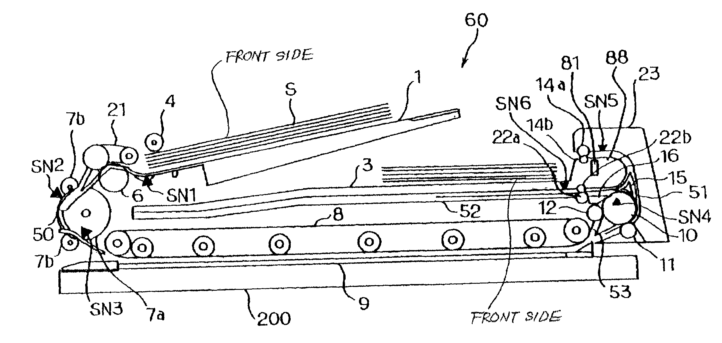
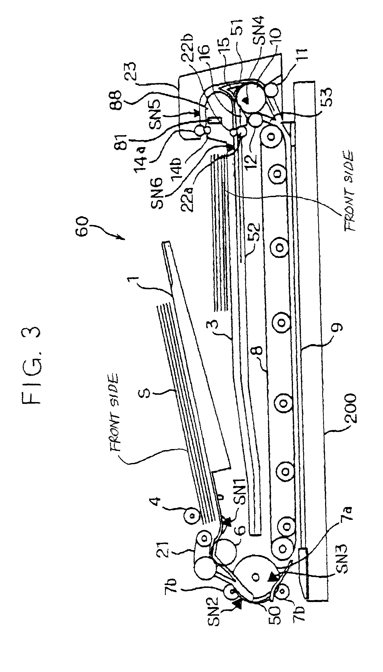
[0048]Referring to FIGS. 3 through 5, an image forming apparatus embodying the present invention will be described. As shown, the ADF, generally 60, is mounted on the apparatus body 200 of the image forming apparatus and generally made up of a feeding section, a conveying section, and a reversing / discharging section. A feed motor 300, a conveyance motor 31 and a discharge motor 32 are respectively assigned to the above three sections. The ADF 60 includes a feed tray 1, a receipt tray 3, a pickup roller 4, a belt 21, a reverse roller 6, pullout rollers 7a and 7b, a belt 8, and a glass platen 9. The ADF 60 further includes a first discharge drive roller 10, a first discharge driven roller 11, a reverse / discharge roller 12, a second discharge drive roller 14a, a second discharge driven roller 14b, an outlet guide 88, a first path selector 15, a second path selector 16, a switchback drive roller 22a, and a switchback driven roller 22b. The ADF 60 additionally includes a set sensor SN1, ...

second embodiment

[0088]An alternative embodiment of the present invention will be described hereinafter. This embodiment is generally identical with the previous embodiment except for the configuration of the first discharge drive roller 10. In the figures, identical reference numerals designate identical structural elements. The following description will concentrate on the difference between this embodiment and the previous embodiment.

[0089]In the illustrative embodiment, an electromagnetic clutch is substituted for the gear Z5 of the discharge drive roller 10. When the document S jams the path with its trailing edge left in the conveying section, the electromagnetic clutch allows it to be easily pulled out.

[0090]In operation, when the discharge motor 32 (M), FIG. 14, is in rotation, the ADF controller 29 couples the electromagnetic clutch substituted for the gear Z5. As a result, the rotation of the discharge motor 32 is transferred to the discharge drive roller 10. While the discharge motor 32 i...

third embodiment

[0092]Another alternative embodiment will be described with reference to FIGS. 20 through 24. This embodiment is similar to the first embodiment except that the first path selector 15 is mounted on the openable outlet cover 23, in that part of the receipt tray 3 is angularly movable about a fulcrum 3c, and that the entire receipt tray 3 is angularly movable about a fulcrum 3d. This configuration allows the document S jamming the conveying section or the discharging section to be easily removed.

[0093]Specifically, the outlet cover 23 with the first path selector 15 can be opened to the position shown in FIG. 20. The outlet cover 23 plays the role of a sheet guide facing the first discharge drive roller 10 when closed. The outlet cover 23 therefore uncovers the path around the discharge drive roller 10 when opened. For example, assume that the document S jams the path with its leading edge nipped between the discharge drive roller 10 and the discharge driven roller 11 and with its tra...


PUM


Abstract

An ADF (Automatic Document Feeder) of the present invention includes a path for conveying a document from a scanning position, reversing the document to switch it back, and again reversing the document to thereby convey it toward a receipt tray positioned below a feed tray. Another path conveys the document away from the scanning position, reverses the document, and then conveys it to the receipt tray. Two path selectors selectively steer the document to either one of the above two paths. In both of a one-side mode and a both-side mode, the document is driven out of the ADF to the same receipt tray. The ADF promotes rapid conveyance and facilitates the removal of a jamming document.

Description

BACKGROUND OF THE INVENTION[0001]1. Field of the Invention[0002]The present invention relates to an ADF (Automatic Document Feeder) for sequentially conveying documents stacked on a feed tray while separating them one by one, and an image forming apparatus including the same.[0003]2. Description of the Background Art[0004]Japanese Patent Laid-Open Publication No.11-192374, for example, discloses an ADF including two receipt trays respectively assigned to a one-side mode and a both-side mode. The one-side mode and both-side mode refer to the conveyance of a document carrying an image on one side and that of a document carrying images on both sides, respectively. The two receipt trays allow documents to be sequentially driven out of the ADF in order of page while promoting rapid conveyance.[0005]Japanese Patent Laid-Open Publication No. 8-110662 proposes an ADF also including two trays respectively assigned to the one-side mode and both-side mode. The tray for the one side mode is pos...

Claims


Application Information

Patent Timeline
Patent Type & Authority Patents(United States)
IPC IPC(8): H04N1/04G03G15/00B65H7/06B65H29/58B65H29/60B65H85/00G03G15/23H04N1/00
CPCG03G15/231
Inventor SEKINE, NORIAKI
Owner RICOH KK
Why Eureka
Try Eureka