Hard disk anchoring apparatus

a technology for anchoring apparatus and hard disks, which is applied in the direction of electrical apparatus casings/cabinets/drawers, instruments, lighting support devices, etc., can solve the problems of inability to adopt the anchoring structure of removable hard disks, laborious installation and removal operations, etc., and achieve the effect of quickly mounting or removing hard disks

Inactive Publication Date: 2006-03-21
INVENTEC CORP
View PDF6 Cites 90 Cited by
  • Summary
  • Abstract
  • Description
  • Claims
  • Application Information

AI Technical Summary

Benefits of technology

[0005]In view of the aforesaid problems, the primary object of the invention is to provide a hard disk anchoring apparatus to mount or remove a hard disks quickly without using tools, and also to be adaptable to removable hard disk rack.

Problems solved by technology

Installing and removing operations of the hard disk are tedious.
All the hard disk mounting devices set forth above aim to mount the hard disk in a chassis, but cannot be adopted on removable hard disk anchoring structures.

Method used


Image

  • Hard disk anchoring apparatus
  • Hard disk anchoring apparatus
  • Hard disk anchoring apparatus

Examples


Embodiment Construction

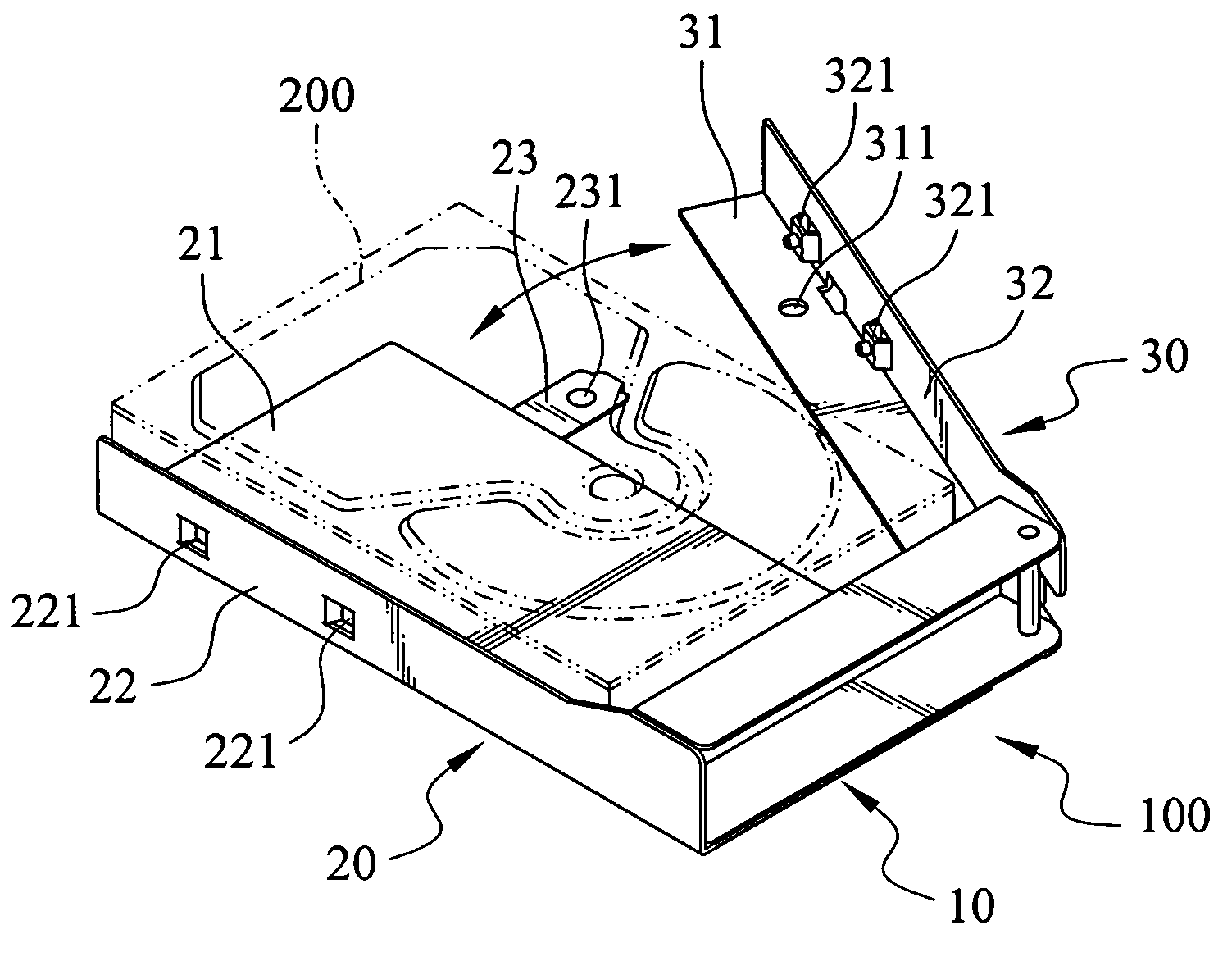
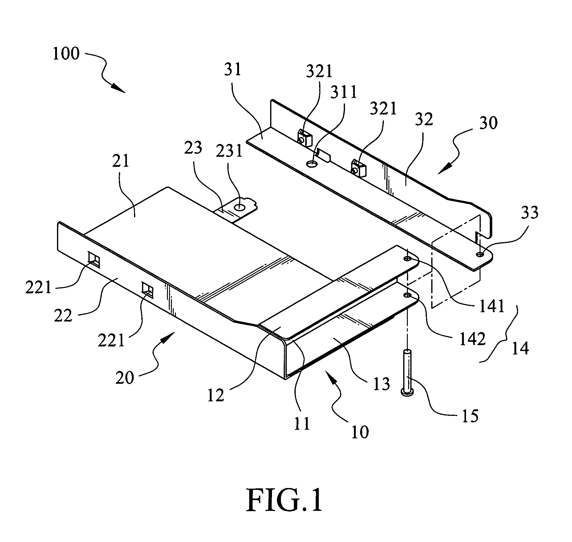
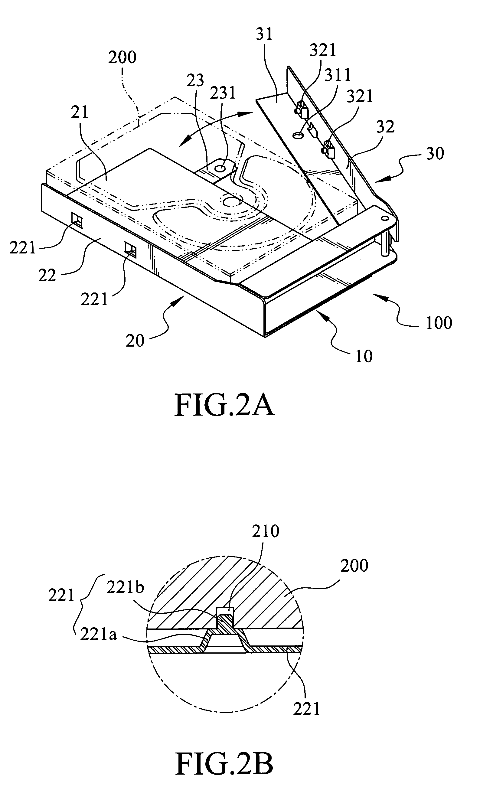
[0018]Refer to FIG. 1 for a first embodiment of the invention. The hard disk anchoring apparatus 100 aims to retain a hard disk 200 with a plurality of screw holes 210.

[0019]The hard disk anchoring apparatus 100 comprises a coupling seat 10 witch has a rectangular front wall 11. A top slab 12 and a bottom slab 13 extend perpendicularly from the opposite edges of the front wall 11. The top slab 12 and the bottom slab 13 have respectively pivot holes 141 and 142 on their edges close to the short side of the front side wall 11 to form a first hinge section 14. An axle 15 can pass through the first hinge section 14.

[0020]A fixed bracket 20 is fixedly mounted to the coupling seat 10. The fixed bracket 20 has a fixed bottom plate 21 and a fixed side wall 22 with two first fasteners 221.

[0021]A movable bracket 30 has a movable bottom plate 31 and a movable side wall 32. The movable bottom plate 31 has a second hinge section 33 on one side that is a round hole, and is coupled with the first...


PUM


Abstract

A hard disk anchoring apparatus for retaining a hard disk with a plurality of screw holes includes a coupling seat, a fixed bracket and a movable bracket. The fixed bracket is fixedly coupled with the coupling seat. The movable bracket is movably hinged on the coupling seat. A coupling blade is provided to couple the fixed bracket and the movable bracket. The fixed bracket and the movable bracket each have fasteners matching the screw holes formed on two sides of the hard disk. The movable bracket may be swiveled to close to the fixed bracket and coupled through the coupling blade. Thus the hard disk is retained by latching the movable bracket and the fixed bracket.

Description

FIELD OF THE INVENTION[0001]The invention relates to mount a hard disk in a computer chassis, and particularly to a toolless hard disk anchoring apparatus for installing and removing a hard disk without tools.BACKGROUND OF THE INVENTION[0002]The conventional approach now being adopted to mount a hard disk in a computer chassis generally involves placing the hard disk in a holding area of a drive bracket; screwing a plurality of screws through side walls of the drive bracket into two sides of the hard disk body to fasten the hard disk on the drive bracket; and mounting the hard disk and the frame in a computer chassis or a mobile hard disk rack. For the steadiness of the hard disk and balance fastening of the screws, multiple screws have to be fastened at the same time. Installing and removing operations of the hard disk are tedious.[0003]To remedy the aforesaid disadvantages, improved designs for fastening and removing the hard disk to and from the anchor frame with few screws have ...

Claims


Application Information

Patent Timeline
Patent Type & Authority Patents(United States)
IPC IPC(8): G06F1/16H05K7/00
CPCG06F1/184G11B33/124G11B33/022G06F1/187
Inventor CHANG, LIN-WEI
Owner INVENTEC CORP
Why Eureka
Try Eureka