Image forming apparatus having device for charging a photosensitive body

a photosensitive body and charging technology, applied in the direction of electrographic process apparatus, corona discharge, instruments, etc., can solve the problems of difficult to achieve dispersion, the charge potential on the photosensitive body is not constant, and the film thickness deviation is not rare. to provide a deviation of 1 through 2 m, and achieve the effect of uniform charge potential

Inactive Publication Date: 2006-03-21
SEIKO EPSON CORP
View PDF11 Cites 5 Cited by
  • Summary
  • Abstract
  • Description
  • Claims
  • Application Information

AI Technical Summary

Benefits of technology

[0015]It is an object of the invention to resolve the above-described problem and provide an image forming apparatus capable of achieving uniform formation of a charge potential at a surface of a photosensitive body by a simple constitution.

Problems solved by technology

Although the dipping coating method is more excellent in film thickness stability than a ring coating method or the like, even with the dipping coating method, it is not rare to provide a film thickness deviation of 1 through 2 μm between an upper portion and a lower portion of dipping.
Further, even when the insulator sheet is pasted on the inner face of the back plate such that the pasting rate at the two end portions becomes larger than that of the central portion, the charge potential on the photosensitive body does not become constant.
This is the difference which cannot be disregarded in consideration of a request for high image quality formation in forming a color image of recent times. Normally, in order to achieve an excellent color image in an image forming apparatus, it is desired to make an in-plane dispersion of the charge potential (dispersion in the axis line direction of the photosensitive body) equal to or lower than 20 V, however, it is difficult to achieve the dispersion owing to an influence of a tolerance or the like of a part constituting the charger and it is a significant problem that the potential difference in the axis line direction of the photosensitive body becomes about 5 through 12 V from the start under such a situation.

Method used


Image

  • Image forming apparatus having device for charging a photosensitive body
  • Image forming apparatus having device for charging a photosensitive body
  • Image forming apparatus having device for charging a photosensitive body

Examples


first embodiment

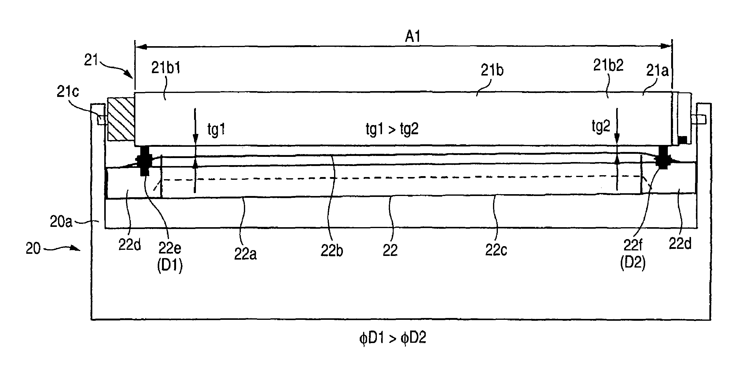
[0101] explained here, as shown by FIGS. 4A and 4B, the charger 22 is a scorotron charger having a discharge electrode 22a and a grid 22b and by slightly inclining a total of the charger 22 to an axis line of the photosensitive body 21, an interval between the grid 22b and a surface of the photosensitive body 21 is narrowed on a side of the dip upper portion 21b2 of the photosensitive body 21 (the interval is designated by notation tg2) and widened on a side of the dip lower portion 21b1 (the interval is designated by notation tg1).

[0102]Further, FIG. 4A is a graph showing a change in the film thickness of the photosensitive layer 21b in the axis line direction of the photosensitive body 21 and FIG. 4B is an outline view of the image carrier unit 20.

[0103]Notation 20a designates a case of the image carrier unit 20, the photosensitive body 21 is rotatably supported by the unit case 20a at a shaft 21c thereof and is driven to rotate by a drive mechanism, not illustrated. Notation A1 d...

third embodiment

[0127]Although the both sides of the charger 22 are provided with the pair of spacers 22e, 22e for rectifying the interval between the surface of the photosensitive body 21 and the charger 22 by being brought into contact with the surface of the photosensitive body 21 similar to the above-described third embodiment, the spacers 22e, 22e according to the embodiment are provided with the same diameter (D) and the charger 22 per se is not inclined.

[0128]Operation and effect similar to those of the above-described third embodiment are achieved also by the embodiment.

[0129]Further, according to the embodiment, it is not necessary to incline the charger 22 per se and therefore, assembling performance is promoted.

[0130]FIGS. 9A through 9c are views showing an essential portion of a fifth embodiment of the image forming apparatus according to the invention, FIG. 9A is a graph showing a change in the film thickness of the photosensitive layer 21b in the axis line direction of the photosensit...

fourth embodiment

[0131]A point of the embodiment which differs from the above-described fourth embodiment resides in that by not changing the heights of the grid supporting portions but changing heights of electrode supporting portions 22d5 and 22d6 for supporting both sides of the discharge electrode 22a, the interval between the discharge electrode 22a and the surface of the photosensitive body is narrowed on the side of the dip upper portion 21b2 of the photosensitive body 21 (the interval is designated by notation tw4) and widened on the side of the dip lower portion 21b1 (the interval is designated by notation tw3) and the other points remain unchanged.

[0132]As shown by FIG. 9C, the electrode supporting portions 22d5 and 22d6 are respectively provided at the supporting members 22d on both sides and by making a height hw2 of the electrode supporting portion 22d6 on the side of the dip upper portion 21b2 of the photosensitive body 21 slightly higher than a height hw1 of the electrode supporting p...


PUM


Abstract

An image forming apparatus having a charger of a non-contact type opposed to a photosensitive body coated with a photosensitive layer by dipping for charging a surface of the photosensitive body and an interval between the surface of the photosensitive body and the charger is narrowed on a dip upper portion side of the photosensitive body and widened on a dip lower portion side thereof. When the charger is a scorotron charger having a discharge electrode and a grid, an interval between the grid and the surface of the photosensitive body is narrowed on the dip upper portion side of the photosensitive body and widened on the dip lower portion side.

Description

[0001]The present application is based on Japanese Patent Applications Nos. 2002-303904, 2002-303905, 2002-303906 and 2002-303907, the entire contents of which are incorporated herein by reference.BACKGROUND OF THE INVENTION[0002]1. Field of the Invention[0003]The present invention relates to an image forming apparatus of a printer, a facsimile, a copier or the like for forming an image by using an electrophotography technology. Particularly, the invention relates to a charging technology for charging a photosensitive body thereof.[0004]2. Related Art[0005]Generally, an image forming apparatus using electrophotography technology includes a photosensitive body having a photosensitive layer at an outer peripheral face thereof, a charging unit for uniformly charging the outer peripheral face of the photosensitive body, an exposing unit for forming an electrostatic latent image by selectively exposing the outer peripheral face charged uniformly by the charging unit, a developing unit fo...

Claims


Application Information

Patent Timeline
Patent Type & Authority Patents(United States)
IPC IPC(8): G03G15/00G03G15/02
CPCG03G15/0291G03G2215/027
Inventor MAEDA, MASAHIROINABA, ISAONAKATA, MASANORI
Owner SEIKO EPSON CORP
Why Eureka
Try Eureka