Pneumatic locking swivel caster

a swivel caster and pneumatic locking technology, applied in the field of improved caster equipment, can solve the problems of ineffective and awkward steps on the caster brakes, and the inability to effectively stop in a fixed position and orientation

Inactive Publication Date: 2006-03-28
SILVERSTEIN HARLAN +1
View PDF13 Cites 73 Cited by
  • Summary
  • Abstract
  • Description
  • Claims
  • Application Information

AI Technical Summary

Benefits of technology

[0017]These and other embodiments

Problems solved by technology

One of the ongoing problems in the theatre is how to secure props and scenery elements on the stage quietly and quickly and to then be able to move them also quietly and quickly.
This is very expensive.
It is also impractical when more than one production might be performed on the same stage during the same season.
Smaller prop units can be mounted on cast

Method used


Image

  • Pneumatic locking swivel caster
  • Pneumatic locking swivel caster
  • Pneumatic locking swivel caster

Examples


example 1

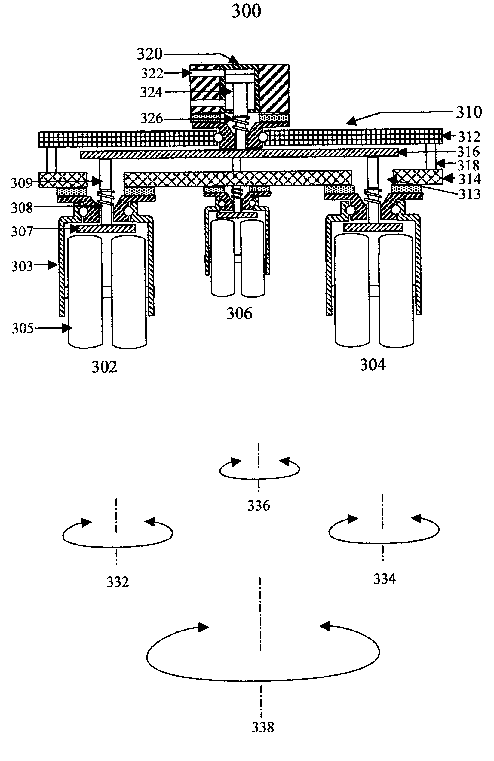
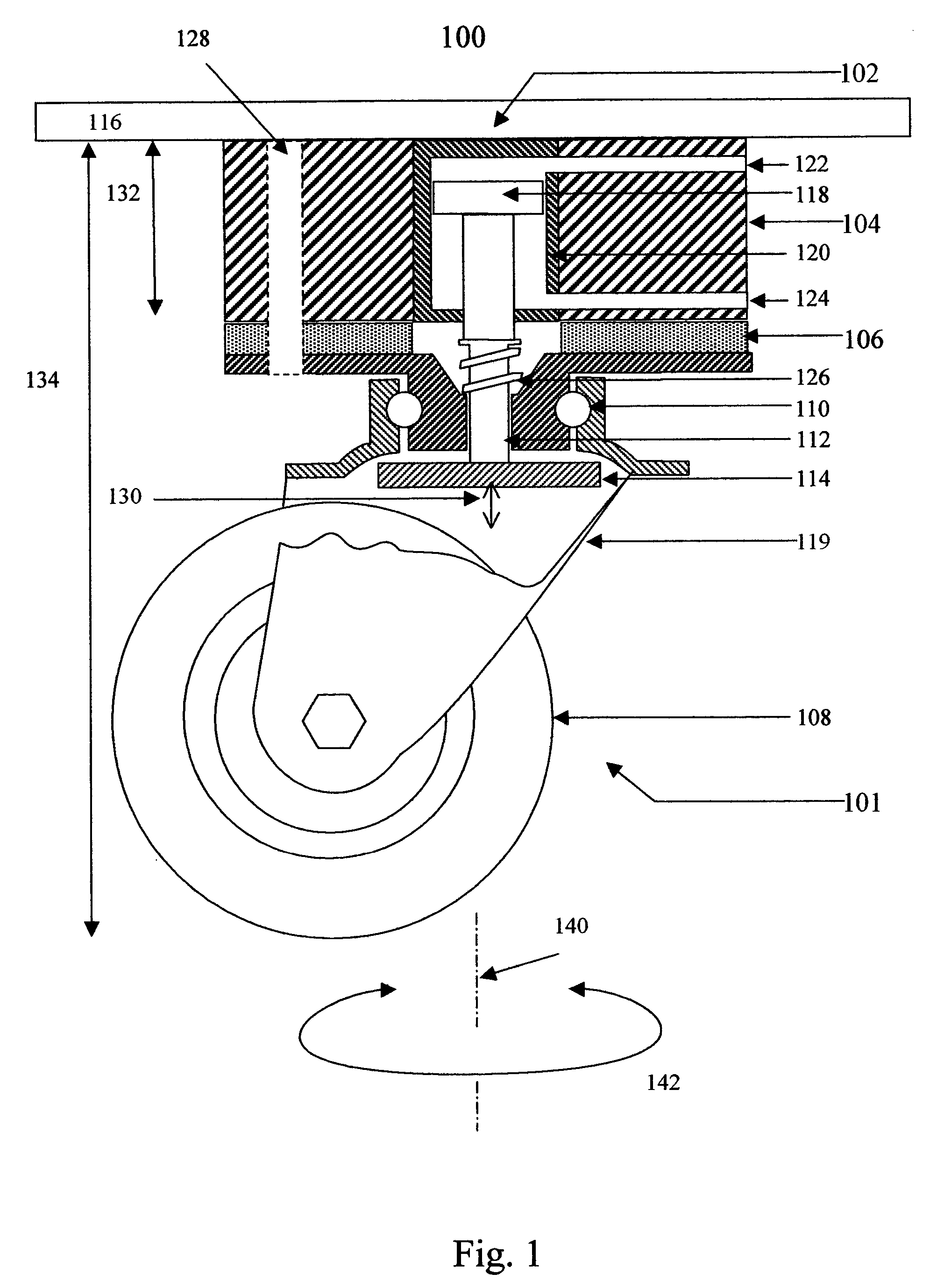
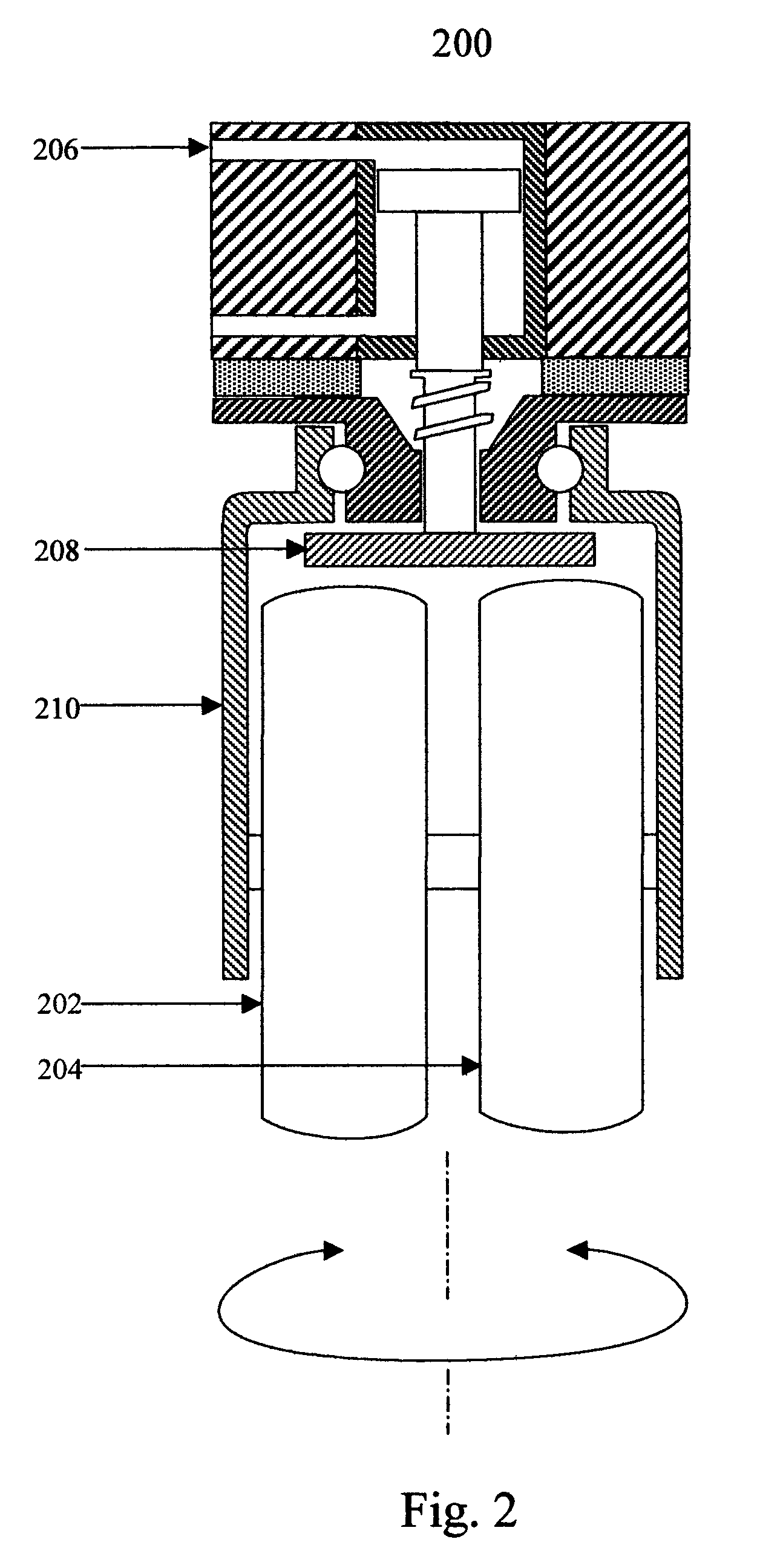
[0076]Four dual wheel embodiments of a pneumatic locking swivel caster and a control system are mounted on a grand piano stage prop body. The high pressure gas supply comprises a metal tank with a volume of two cubic feet (50 liters). The tank is pressurized with air to 100 psig (7 atmospheres). The high pressure air supply further comprises a regulator that reduces the pressure in the first gas line to 40 psig (2.7 atmospheres). The activation valve is a mechanical three way valve. Each piston in the pneumatic locking swivel casters has a diameter of about one inch (2.5 cm). The height of the pneumatic locking swivel casters from the bottom of the wheels to the top of the mounting block is 5.5 inches (14 cm). The combined thickness of the mounting block and spacer is 1.5 inches (3.8 cm). There are four mounting holes in each mounting block. The mounting holes have a diameter of 5 / 16 inch (0.79 cm).

[0077]When the switch is turned on, 40 psig of gas pressure is delivered to the caste...


PUM


Abstract

A pneumatic locking swivel caster comprises a swivel caster and a locking device which may be activated by fluid pressure. The swivel caster may be a dual wheel swivel caster. An improved theatrical prop or scenery element comprises a pneumatic locking swivel caster and a control system. The control system may comprise a tank filled with pressurized air and a control valve. A pneumatic locking swivel caster may be locked into position by activating the control valve and pressuring the caster with air. The pneumatic locking swivel caster may comprise a triple swivel caster adapted such that all three sets of wheels are locked by air pressure.

Description

CROSS REFERENCE TO RELATED APPLICATION[0001]This application claims the benefit of the filing date of U.S. provisional application entitled, “Pneumatic Locking Swivel Caster”, Ser. No. 60 / 415,661, filed Oct. 2, 2002 and which is incorporated herein by reference.FIELD OF INVENTION[0002]This invention relates to an improved caster apparatus and method for moving theatre scenery props and locking them into position.BACKGROUND[0003]One of the ongoing problems in the theatre is how to secure props and scenery elements on the stage quietly and quickly and to then be able to move them also quietly and quickly.[0004]One method for doing this with large scenery elements and props is to move them with an automatic winch. This is very expensive. It is also impractical when more than one production might be performed on the same stage during the same season.[0005]Smaller prop units can be mounted on casters, but these are harder to stop effectively in a fixed position and orientation. Wedges an...

Claims


Application Information

Patent Timeline
IPC IPC(8): B60B33/06B60B33/02
CPCB60B33/0005B60B33/0015B60B33/0042B60B33/0049B60B33/0057B60B33/0068B60B33/0081B60B33/0092B60B33/021B60B33/0073Y10T16/182Y10T16/18Y10T16/195Y10T16/202
Inventor SILVERSTEIN, HARLANSCHWARTZ, GARY
Owner SILVERSTEIN HARLAN
Why Eureka
Try Eureka