Method and apparatus for gas ranges

Inactive Publication Date: 2006-03-28
HAIER US APPLIANCE SOLUTIONS INC
View PDF10 Cites 40 Cited by
  • Summary
  • Abstract
  • Description
  • Claims
  • Application Information

AI Technical Summary

Problems solved by technology

However, producing a burner with various sized burner ports can be difficult to design, detrimental to various performance

Method used


Image

  • Method and apparatus for gas ranges
  • Method and apparatus for gas ranges
  • Method and apparatus for gas ranges

Examples


Embodiment Construction

[0022]While the methods and apparatus are herein described in the context of a gas-fired cooktop, as set forth more fully below, it is contemplated that the herein described method and apparatus may find utility in other applications, including, but not limited to, gas heater devices, gas ovens, gas kilns, gas-fired meat smoker devices, and gas barbecues. In addition, the principles and teachings set forth herein may find equal applicability to combustion burners for a variety of combustible fuels. The description hereinbelow is therefore set forth only by way of illustration rather than limitation, and any intention to limit practice of the herein described methods and apparatus to any particular application is expressly disavowed.

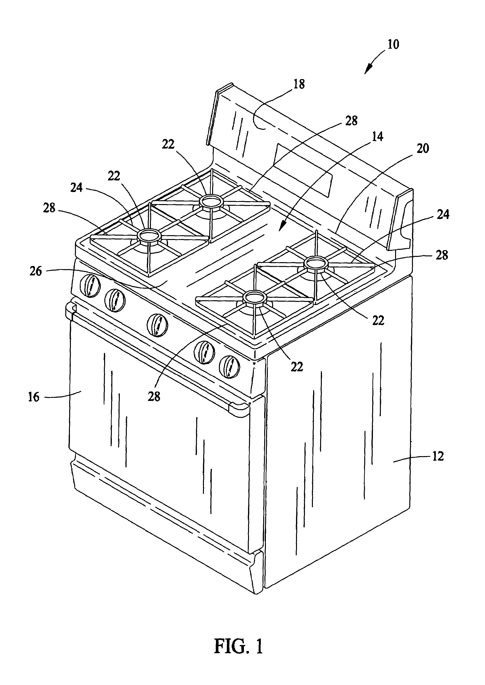
[0023]FIG. 1 illustrates an exemplary free standing gas range 10 in which the herein described methods and apparatus may be practiced. Range 10 includes an outer body or cabinet 12 that incorporates a generally rectangular cooktop 14. An oven, not shown, ...


PUM


Abstract

A gas burner assembly for connection to a source of gas includes a burner body including at least one receptacle, a burner cap positioned on the burner body, at least two isolation walls coupled to the burner body, and at least one projection extending from the burner cap. The projection is configured to allow substantially uniform gas distribution through a plurality of burner ports at a first gas input rate, and configured to limit the gas distribution to at least one burner port at a second input rate greater than the first input rate input rate.

Description

BACKGROUND OF THE INVENTION[0001]This invention relates generally to a method an apparatus for gas burners, and, more particularly, a method and apparatus for gas surface burners used in a gas cooking product.[0002]Gas surface burners used in cooking products typically include a burner base, a burner head including a plurality of burner ports through which a gas is distributed, and a burner cap positioned over the burner head. At least some known burners include a plurality of burner ports in the base. At least some known burners include a cap and a burner head that are physically integrated. Other known burners include a cap and a head that are coupled and then positioned over the burner base. Both designs often include a circular region of increased gas volume near the burner ports. This area of increased gas volume facilitates allowing angular variations in pressure to equalize such that a gas flow through each burner port is approximately equal. Typically, when a reduced flow th...

Claims


Application Information

Patent Timeline
IPC IPC(8): F24C3/00F23D14/06
CPCF23D14/06F23D14/70
Inventor CADIMA, PAUL BRYAN
Owner HAIER US APPLIANCE SOLUTIONS INC
Why Eureka
Try Eureka