Fuel cell apparatus and methods

Inactive Publication Date: 2006-11-02
LILLIPUTIAN SYST
View PDF11 Cites 40 Cited by
  • Summary
  • Abstract
  • Description
  • Claims
  • Application Information

AI Technical Summary

Benefits of technology

[0008] Fuel efficiency is achieved, in part, by regulating thermal efficiency. Specifically, improved thermal efficiency results, in part, from any one or a combination of the following factors: integration of the fuel reformer, fuel cell, and tail gas burner into a single, essentially isothermal, zone of high temperature; substantially reducing the heat dissipation area of the hot zone by increasing the power density in the fuel cell stack, preferably to values in excess of 2 W/cc; use of an efficient (either aerogel or vacuum) means of thermal insulation such that all of the com

Problems solved by technology

However, solid-oxide fuel cells, require membrane and catalytic operation at temperatures in excess of 600° C., often in excess of 750° C. Consequently, designers of solid-oxide fuel cells for portable power applications must protect the end user from the extreme heat without adding excessively to the size of the overall system.
Such a system cannot be more than 10% efficient, i.e., the system uses more than 90% of the fuel energy for t

Method used


Image

  • Fuel cell apparatus and methods
  • Fuel cell apparatus and methods
  • Fuel cell apparatus and methods

Examples


Embodiment Construction

[0035] The following description refers to the accompanying drawings that illustrate certain embodiments of the present invention. Other embodiments are possible and modifications may be made to the embodiments without departing from the spirit and scope of the invention. Therefore, the following detailed description is not meant to limit the present invention. Rather, the scope of the present invention is defined by the appended claims.

[0036] It should be understood that the order of the steps of the methods of the invention is immaterial so long as the invention remains operable. Moreover, two or more steps may be conducted simultaneously unless otherwise specified.

Integrated Fuel Cell Apparatus, Package, and Connections

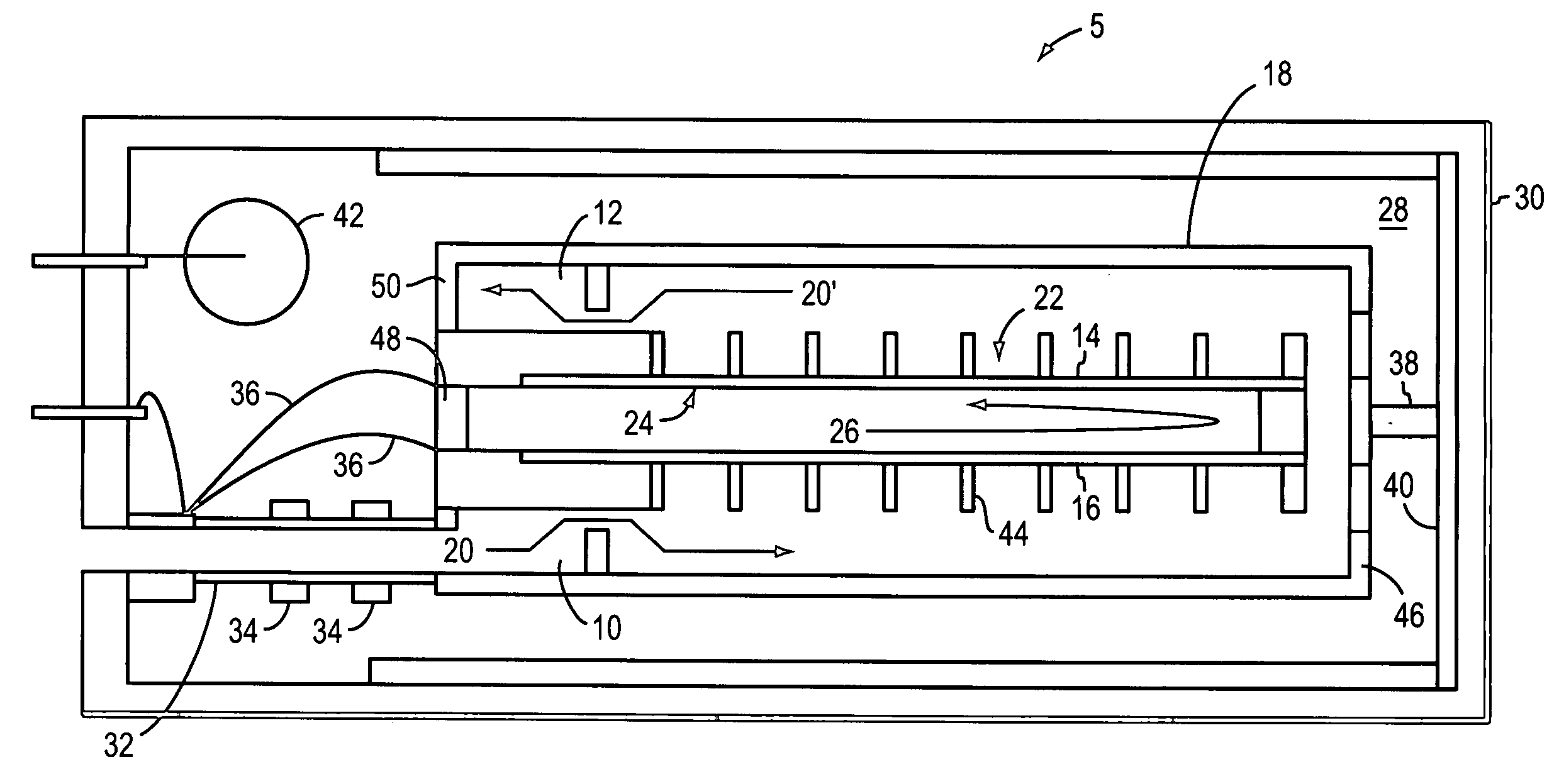
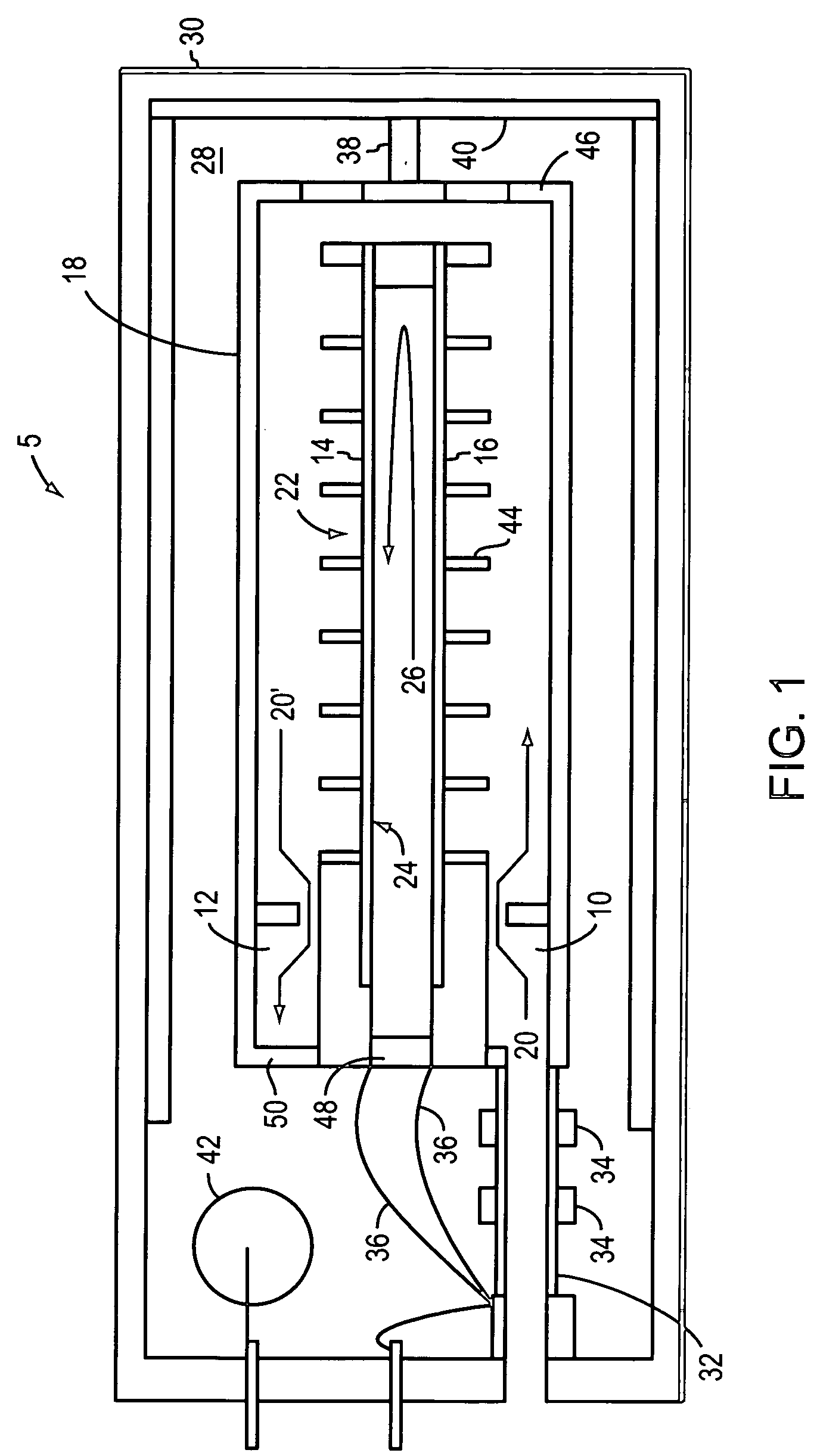
[0037] The fuel cell apparatus embodiments described herein can produce electrical power in excess of 2 W / cc and in excess of 3 W / cc. Such fuel cell apparatus are uniquely capable of producing insulated package sizes small enough for portable application, even ...


PUM


Abstract

The invention relates to a fuel cell apparatus that includes a housing. The housing defines a substantially isothermal zone which integrates a fuel cell and a tail gas burner with the isothermal zone. The fuel cell and the tail gas burner are in thermal communication and share a common wall. In one embodiment, the housing further integrates a fuel reformer, where the fuel reformer is in thermal communication with the fuel cell. In one embodiment, the fuel cell and the tail gas burner can be arranged to produce a power density greater than or equal to about 2 W/cc. The fuel cell preferably is a solid oxide fuel cell.

Description

TECHNICAL FIELD [0001] The invention relates to apparatus and methods that improve fuel cell efficiency. In one embodiment, the invention relates to fuel cells adapted for improving energy balance by integrating multiple fuel cell components in an isothermal zone. BACKGROUND [0002] Fuel cells that operate in conjunction with replaceable fuel canisters filled with, for example, gaseous hydrogen, methanol, butane or diesel fuel, are a developing technology. These types of fuel cells are designed to compete with the various battery solutions that power consumer products. The competitiveness of these fuel cells with regard to batteries depends on a number of factors, such as the energy density of the fuel in the canister; the ability of the fuel cell to convert chemical energy to electrical energy with certain efficiencies; and the need to keep the fuel cell stack, along with associated fluid pumping and power control components, no larger than that of a competitive battery. [0003] Impr...

Claims


Application Information

Patent Timeline
IPC IPC(8): H01M8/04H01M8/12
CPCH01M8/04022H01M8/04052H01M8/04067H01M8/04074H01M8/0625H01M8/1286H01M8/2475H01M2008/1293H01M2250/30Y02B90/10Y02E60/50H01M8/2432H01M8/24H01M8/06H01M8/12
Inventor SCHAEVITZ, SAMUELFRANZ, ALEKSANDERBARTON, ROGER
Owner LILLIPUTIAN SYST
Why Eureka
Try Eureka