Process for the production of furnace black

a furnace black and process technology, applied in the direction of pigmenting treatment, inorganic chemistry, chemistry apparatus and processes, etc., can solve the problems of only obtaining the colour depth of the furnace black, and the physical and chemical processes that take place during the formation of carbon blacks are very complex

Inactive Publication Date: 2004-10-28
UBS AG
View PDF8 Cites 39 Cited by
  • Summary
  • Abstract
  • Description
  • Claims
  • Application Information

AI Technical Summary

Problems solved by technology

The physical and chemical processes that take place during carbon black formation are very complex.
The known process has the disa

Method used


Image

  • Process for the production of furnace black
  • Process for the production of furnace black

Examples


example

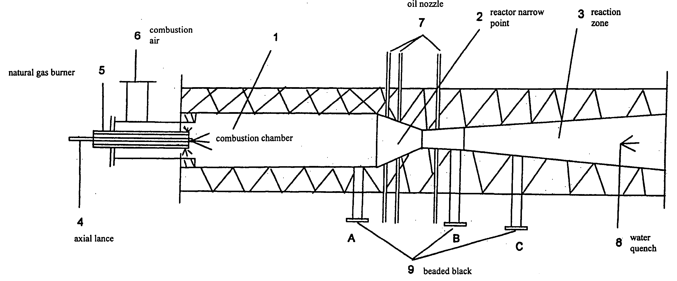
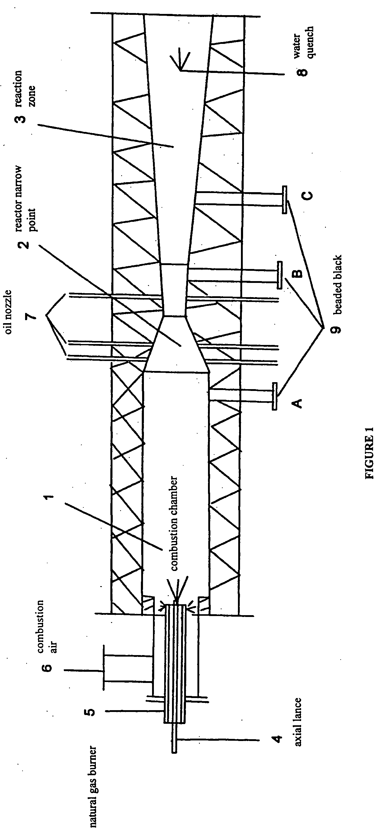
[0020] In a furnace reactor according to FIG. 1, a carbon black is produced with the reactor parameters given in Table 1.

1TABLE 1 Combustion air [Nm.sup.3 / h] 3000 Natural gas [Nm.sup.3 / h] 250 Total steam quantity [kg / h] 3000 Potassium carbonate [kg / h] 8 Combustion chamber temperature [.degree. C.] 1500-1600 Black jetting-in [kg / h] 850 Position of black jetting-in (before narrow point) [mm] 320 Temperature after narrow point [.degree. C.] 1400-1450 Air injector [Nm.sup.3 / h] 200 Temperature at end of reactor [.degree. C.] 700

[0021] The carbon black obtained has the carbon black characteristics given in Table 2.

2TABLE 2 Iodine value [mg / g] DIN 53582 814 BET specific surface [m.sup.2 / g] ASTM D-4820 749 area CTAB surface area [m.sup.2 / g] ASTM D-3765 371 DBP [ml / 100 g] DIN 53601 235 pH value [-] DIN EN ISO 787 / 9 6.2 Oil demand [g / 100 g] DIN EN ISO 787 / 5 690 My value [-] DIN 55979 263 Tint [%] DIN EN ISO 787 / 16 120

[0022] The carbon blacks produced by the process according to the invention ...


PUM


Abstract

Process for the production of furnace black by producing a stream of hot combustion gases in a combustion chamber, feeding the hot combustion gases along a flow axis from the combustion chamber through a reactor narrow point into a reaction zone, mixing carbon black raw material into the flow of the combustion gases in front of, inside or behind the reactor narrow point and stopping carbon black formation downstream in the reaction zone by spraying in water, steam being jetted in axially through the gas burner and optionally at the radial oil nozzles and beaded carbon black being introduced before and/or after the reactor narrow point.

Description

INTRODUCTION AND BACKGROUND[0001] The present invention relates to a process for the production of furnace black.[0002] Furnace blacks are produced in large quantities in carbon black reactors for a wide variety of industrial applications. Carbon black reactors generally consist of combustion chambers, mixing chambers and reaction chambers arranged along the axis of the reactor, which are connected with each other and form a flow path for the reaction media from the combustion chamber through the mixing chamber to the reaction chamber. In the combustion chamber a fuel, normally gas or oil, is burned with the aid of a burner with the addition of pre-heated combustion air, to produce a high temperature. A mostly liquid, carbon-containing raw material, for example a black oil, is sprayed into the hot combustion gases, some of the carbon black raw material being burned and the rest being converted into carbon black and tail gas by thermal cracking. Hydrocarbons with a highly aromatic co...

Claims


Application Information

Patent Timeline
IPC IPC(8): C09C1/50
CPCC09C1/50C01P2006/12
Inventor KOPIETZ, PETERHEINZE, VOLKERMATHIAS, JOHANN
Owner UBS AG
Why Eureka
Try Eureka