Projector exhaust fan

a technology for exhaust fans and projectors, applied in the field of projectors, can solve the problems of inability to ensure the calmness of the projector, the noise level of the exhaust fan itself is high, etc., and achieve the effect of reducing the size of the projector

Inactive Publication Date: 2006-03-28
SEIKO EPSON CORP
View PDF20 Cites 12 Cited by
  • Summary
  • Abstract
  • Description
  • Claims
  • Application Information

AI Technical Summary

Benefits of technology

[0014]In the present invention, the projector has the centrifugal fan, and the inlet of the centrifugal fan is disposed along the plane orthogonal to the optical path plane formed by the light source device, the optical modulator and the projection optical system. Therefore, the exhaust efficiency can be enhanced by efficiently sucking the air inside the projector.
[0031]In this configuration, the light source device, the optical modulator, and the projection optical system are accommodated in the casing for optical components which is substantially U-shaped in plan view. For example, the light source device and the projection optical system are disposed on each end of the substantial U-shape in plan view, and the centrifugal fan is disposed in the vicinity of the light source device. The air can thus be exhausted from the projection side of the projector, any duct to lead the heated air from the centrifugal fan can be omitted, and the size of the projector can be reduced.

Problems solved by technology

Therefore, problems occur in that it is difficult to efficiently suck the air inside the projector by the exhaust sirocco fan, the noise level of the exhaust fan itself becomes high, and calmness of the projector cannot be ensured.

Method used


Image

  • Projector exhaust fan
  • Projector exhaust fan
  • Projector exhaust fan

Examples


Embodiment Construction

[0041]An exemplary embodiment of the present invention will be described below with reference to the drawings.

1. Main Configuration of a Projector

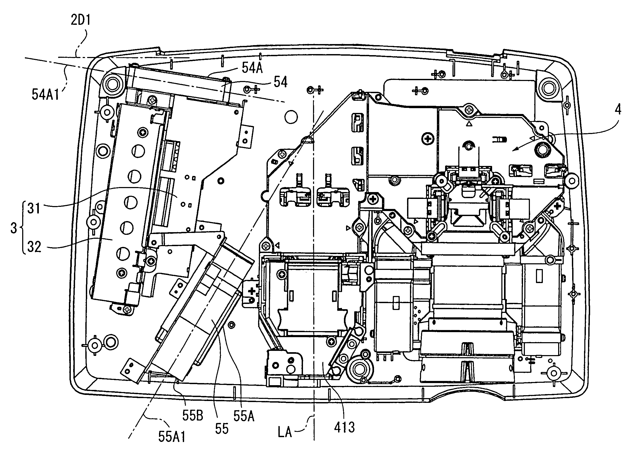
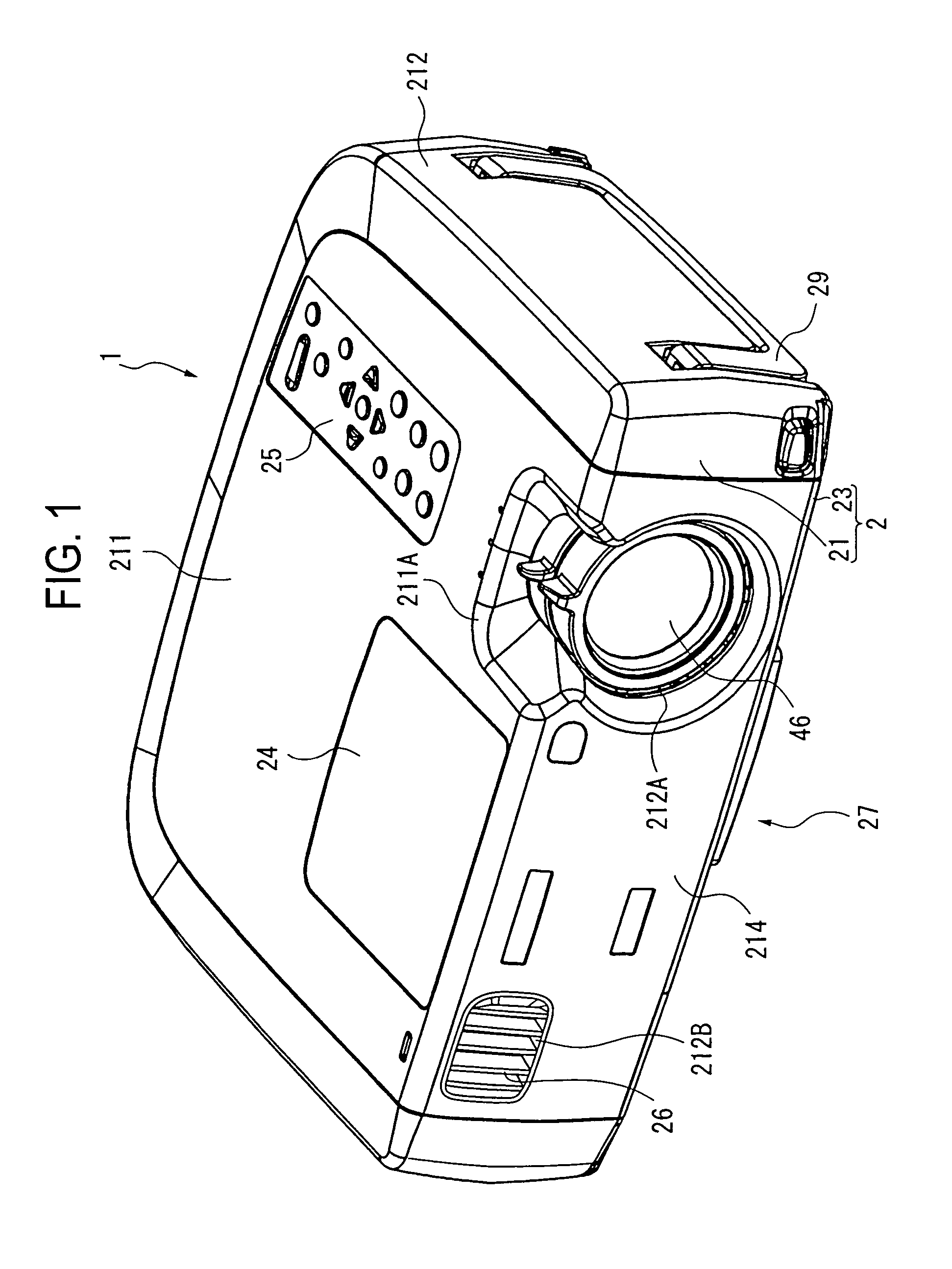
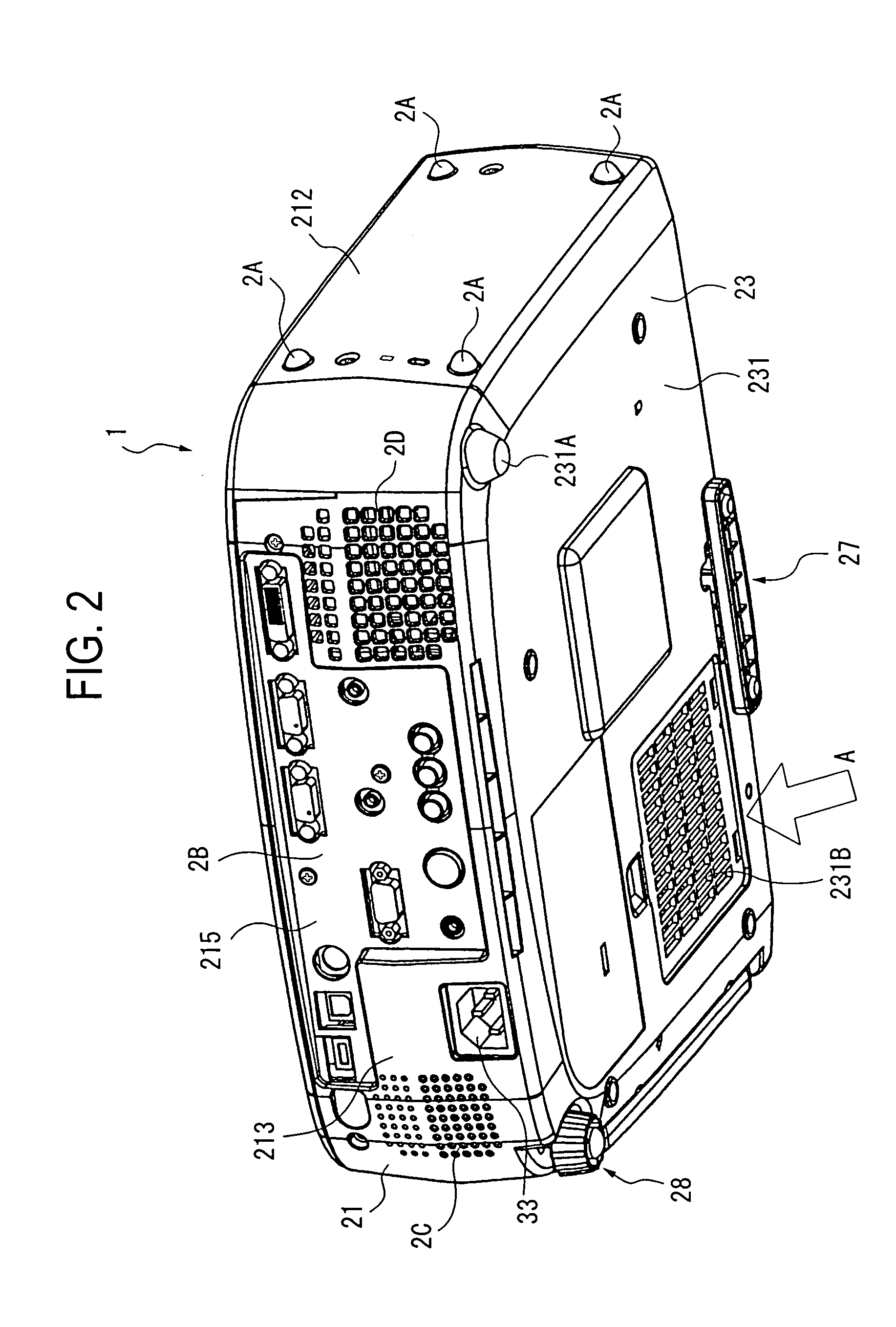
[0042]FIG. 1 is an overall perspective view of a projector 1 according to an exemplary embodiment when viewed from above, FIG. 2 is an overall perspective view of the projector 1 when viewed from below, FIGS. 3 to 5 are perspective views of the inner side of the projector 1. More specifically, FIG. 3 shows the projector 1 in FIG. 1 with an upper case 21 detached therefrom. FIG. 4 shows the projector in FIG. 3 with a shield plate 80 and a driver board 90 detached therefrom. FIG. 5 shows the projector in FIG. 4 with an optical unit 4 detached therefrom. These components 4, 21, 55, 80 and 90 constituting the projector will be described below in detail.

[0043]In FIGS. 1 to 5, the projector 1 includes an exterior case 2, a power source unit 3 accommodated in the exterior case 2, an optical unit 4 of U-shape in plan view similarly disposed in the...


PUM


Abstract

An exhaust sirocco fan exhausts the air inside the projector outside. An inlet of the exhaust sirocco fan is disposed along the plane orthogonal to the optical path plane formed by the optical unit, i.e. along the thickness direction of the projector. In other words, the optical unit or the exhaust sirocco fan need not be disposed in the thickness direction of the projector in an overlapping manner. Therefore, by efficiently sucking the inside air, the exhaust efficiency can be enhanced and calmness can be ensured in the projector.

Description

BACKGROUND OF THE INVENTION[0001]1. Field of Invention[0002]The present invention relates to a projector.[0003]2. Description of Related Art[0004]Hitherto, it has been known that a projector is used during the presentation at conferences, academic meetings, exhibitions, or the like. In such a projector, the light flux emitted from a light source device is modulated by an optical modulator according to image information, to form an optical image, and the optical image is projected in an enlarged manner by a projection optical system.[0005]In such a projector, high brightness of a light source is required in order to sharply display the projected optical image, and the heat generated by the light source must be radiated outside.[0006]Thus, an exhaust structure to exhaust the air heated inside the projector outside by a fan is employed (see Japanese Unexamined Patent Application Publication No. 11-354963, for example).[0007]In the exhaust structure, a centrifugal fan is employed as a f...

Claims


Application Information

Patent Timeline
Patent Type & Authority Patents(United States)
IPC IPC(8): G03B21/16G03B21/14G03B21/18G03B21/26G03B21/00H04N5/74H04N9/31
CPCG03B21/00G03B21/16H04N9/3197H04N9/3144H04N9/3105H04N9/3141G03B21/005
Inventor ITO, SHINSUKEMATSUMIYA, TOSHIO
Owner SEIKO EPSON CORP
Why Eureka
Try Eureka