Local exhaust ventilator with rotating swirler

a local exhaust and swirler technology, applied in ventilation systems, lighting and heating apparatus, heating types, etc., can solve the problems of affecting the efficiency of pollutant removal, and raising the possibility of spreading pollutants farther in the space by blowing flow, so as to achieve the effect of enhancing energy efficiency

Inactive Publication Date: 2005-07-28
POSTECH ACAD IND FOUND
View PDF4 Cites 12 Cited by
  • Summary
  • Abstract
  • Description
  • Claims
  • Application Information

AI Technical Summary

Benefits of technology

[0008] In accordance with the present invention, a local exhaust ventilator is provided that reduces noise due to turbulence-induced interference and removes exhaust gas over a larger area.
[0009] Further in accordance with the present invention, a local exhaust ventilator is provided that involves a simplified structure, an economic production cost, and easy installation, maintenance, and repair.
[0014] In accordance with one form of the present invention, a local exhaust ventilator is provided that increases exhaust efficiency by radial swirl flow entraining air from above an exhaust pipe. A swirler, which is an annular plate with blades, is installed in an exhaust pipe and rotates inside a swirler cover having a peripheral gap along the outer surface of the exhaust pipe and another peripheral gap along the outer rim of the swirler cover.
[0015] Further in accordance with one form of the present invention, a local exhaust ventilator is provided in which a protective cover for the rotating swirler secures the safety of workers moving around under the system. In another exemplary embodiment of the present invention, a local exhaust ventilator includes a swirler, a swirler cover, and a driving unit.
[0019] The gap space between the top cover and the bottom cover of the swirler cover may decrease in height as the distance from the rotational axis of the swirler increases in a radial direction.
[0024] According to one form of the local exhaust ventilator of the present invention, the swirler is operated with the instant generation of a local contamination source, thereby enhancing the energy efficiency. Furthermore, a tornado-like flow is induced due to the interaction thereof with the ground surface, thereby removing the contamination source generated at the ground in an effective manner.

Problems solved by technology

The capture speed necessary for the removal of the pollutants decreases rapidly along the axial direction so that the conventional local exhaust ventilators are not effective to eliminate pollutants occurring far from the exhaust pipe, and, therefore, the exhaust pipe needs to be installed as near to the source of the pollutants as possible.
The near-installed exhaust pipe, however, can be an obstacle to a working line, and is inefficient for pollutant removal due to workers moving around near the exhaust pipe.
Such an exhaust ventilator, however, makes noises resulting from the turbulence generated by the interference between the flow being drawn and the flow being blown in the narrow area under the exhaust pipe, and raises the possibility of spreading the pollutants farther in the space by the blown flow.

Method used


Image

  • Local exhaust ventilator with rotating swirler
  • Local exhaust ventilator with rotating swirler
  • Local exhaust ventilator with rotating swirler

Examples


Embodiment Construction

[0036] The present invention will be described more fully hereinafter with reference to the accompanying drawings, in which various embodiments of the invention are shown.

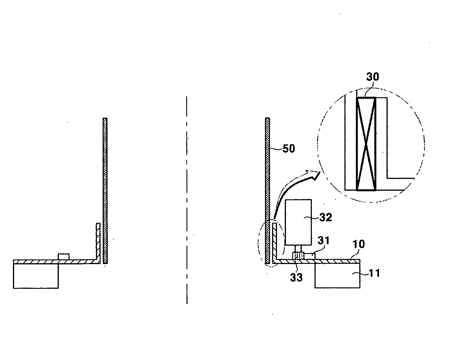
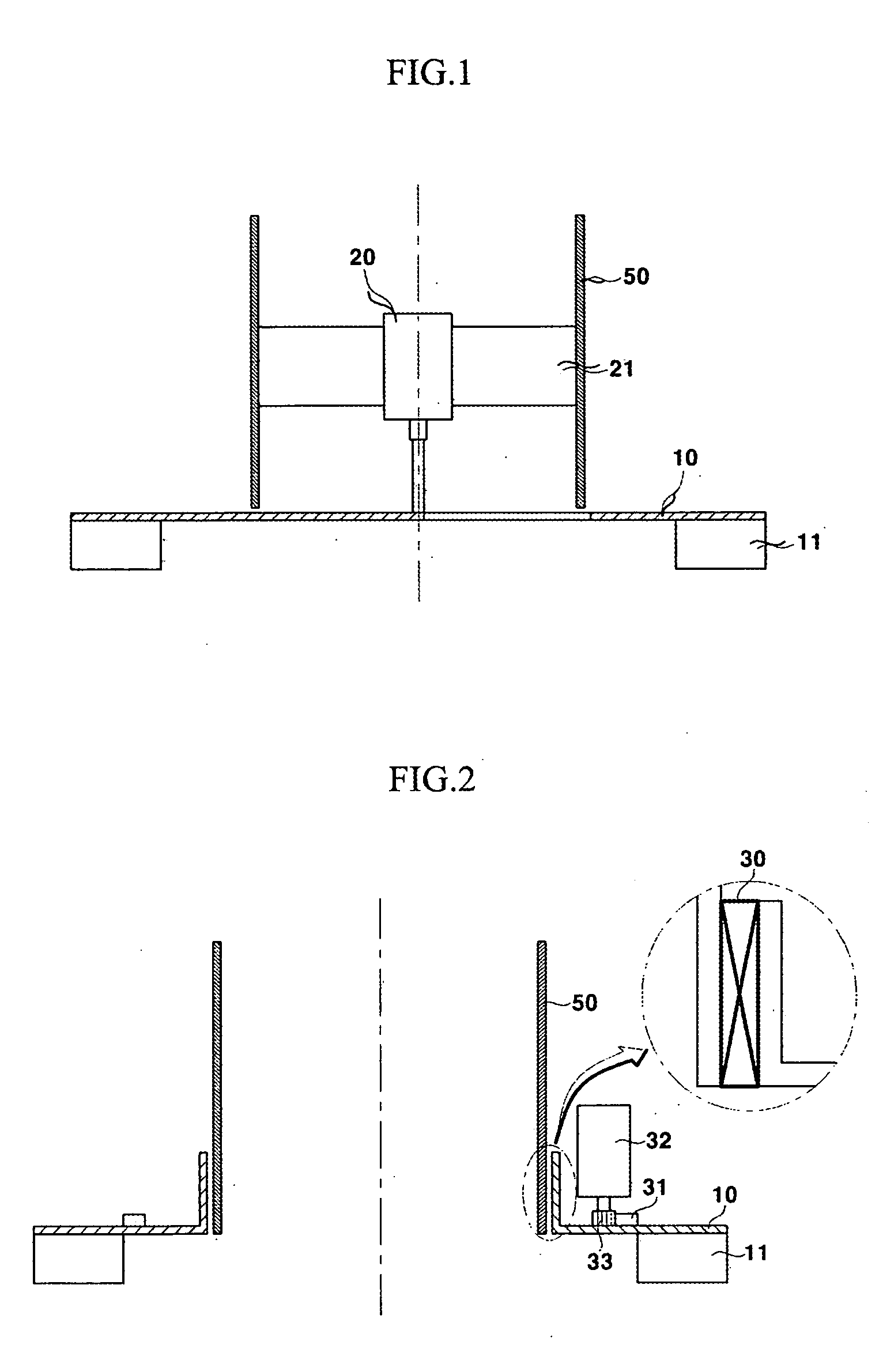
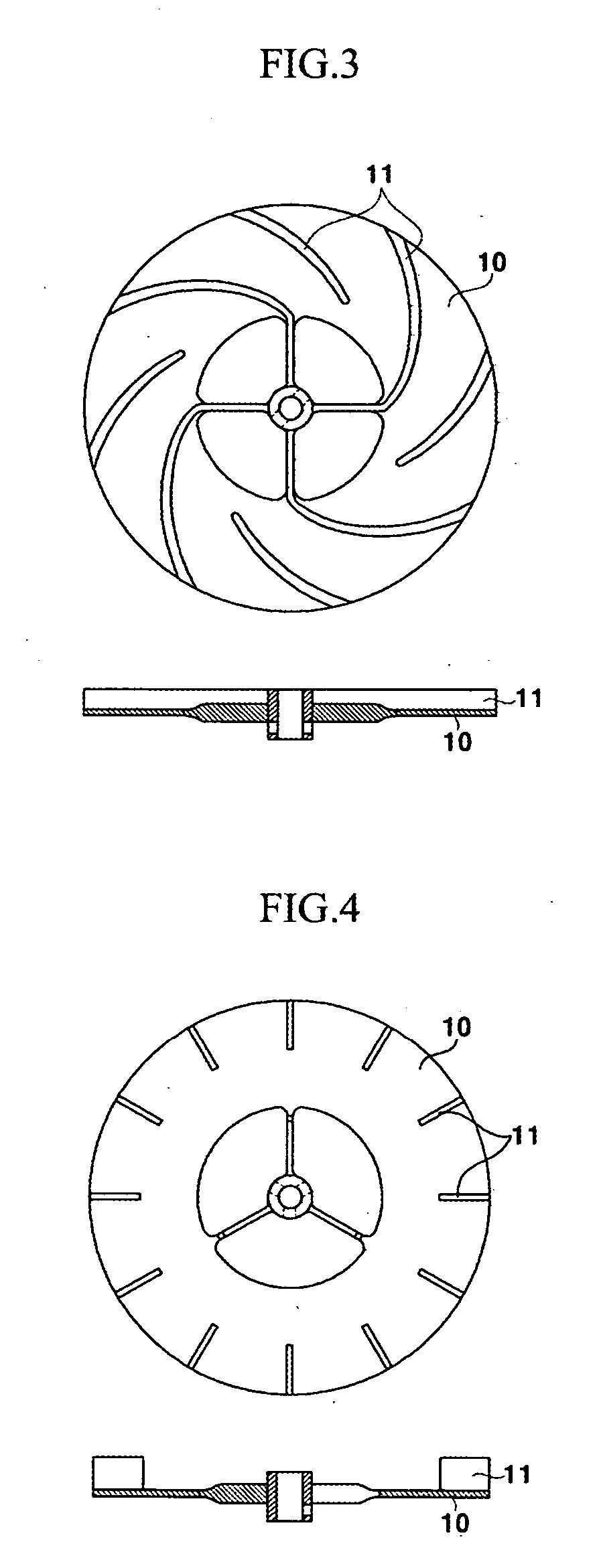
[0037] As shown in FIG. 1, the local exhaust ventilator includes a swirler 10 installed at an exhaust tube 50 to form a swirl flow, and a driving unit for rotating the swirler 10.

[0038] Swirlers are largely classified into an inner drive type and an outer drive type. With the inner drive type shown in FIG. 1, the driving unit is formed with a driving motor 20 fixed to the inner circumference of the exhaust tube 50 via a bracket 21. The swirler 10 rotates around the rotation shaft of the driving motor 20 extended external to the exhaust tube 50 while being fixed thereto.

[0039] Furthermore, with the outer drive type shown in FIG. 2, the swirler 10 is installed at the outer circumference of the exhaust tube 50 via a bearing 30 such that it can be rotated. A circular rack 31 is mounted on the top of the swirler 10. ...


PUM


Abstract

The present invention relates to a local exhaust ventilator which has a rotating swirler to make a swirl flow for increasing exhaust efficiency by expanding an exhaust region. Disclosed is a local exhaust ventilator with a simplified structure, wherein noise due to interference of turbulence is reduced and exhaust gas is removed at a wide area. The local exhaust ventilator includes a disk-shaped swirler rotatably mounted at an exhaust tube, a wing installed at the swirler perpendicular thereto to form a swirl flow, and a driving unit installed at the exhaust tube to rotate the swirler.

Description

BACKGROUND OF THE INVENTION [0001] (a) Field of the Invention [0002] The present invention relates to an exhaust ventilator, and, in particular, to a local exhaust ventilator which has a rotating swirler to produce a swirl flow for increasing exhaust efficiency by expanding an exhaust region. [0003] (b) Description of the Related Art [0004] Generally local exhaust ventilators are utilized in homes, restaurants, and factories that generate pollutants, and, in particular, they can be used where local pollutants are produced far from a main ventilator, where the ventilator is not easily installed near the source of the pollutants, and where the pollutants are produced momentarily. [0005] However, conventional local exhaust ventilators for these purposes have some shortcomings, as follows. The capture speed necessary for the removal of the pollutants decreases rapidly along the axial direction so that the conventional local exhaust ventilators are not effective to eliminate pollutants o...

Claims


Application Information

Patent Timeline
Patent Type & Authority Applications(United States)
IPC IPC(8): F24F7/00F04D25/16F04D29/28F24F7/02
CPCF04D25/166F04D29/281F24F2221/46F24F2007/001F24F7/025F24F7/06F24F13/10
Inventor LEE, SANG MINLEE, JIN WON
Owner POSTECH ACAD IND FOUND
Why Eureka
Try Eureka