Rolled paper holder and image forming apparatus incorporating the same

a technology of image forming apparatus and rolling paper holder, which is applied in the direction of electrographic process, instruments, transportation and packaging, etc., can solve the problems of difficult to achieve a setting which satisfies both conditions, noise generation, and erroneous detection of near-end detectors b>, so as to avoid skewed travel and edge bending of recording medium, less force, and easy loading of recording medium

Active Publication Date: 2006-03-28
SEIKO EPSON CORP
View PDF13 Cites 11 Cited by
  • Summary
  • Abstract
  • Description
  • Claims
  • Application Information

AI Technical Summary

Benefits of technology

[0029]It is therefore an object of the invention to provide a throw-in type rolled paper holder which is capable of preventing the rolled paper from lifting, capable of holding the rolled paper stably to thereby prevent noises from being generated, capable of preventing malfunction of the near-end detector from occurring, and capable of preventing the drawn-out paper from being skewed and bent.
[0046]With the above configurations, the rolled recording medium held in the holder can be rotated with less force, so that the recording medium subjected to the image forming operation can be drawn out from the rolled recording medium smoothly and stably. Further, since the distance between the side wall members are suitably determined relative to the width of the rolled recording member, loading the rolled recording medium is easy, and noises due to the play of the rolled recording medium can be prevented by gaps between the rolled recording medium and the side wall members. Further, skewed travel and edge bending of the recording medium can be avoided.
[0047]In addition, since the contact load of the contact member of the detector is allowed to be increased, the design flexibility of the detector and the holding stability with respect to the rolled recording medium can be increased.

Problems solved by technology

Further, erroneous detection of the near-end detector 40 would occur and noise is generated when the lifted rolled paper 10 returns to the original position thereof and collides with the bottom face 71f.
A problem arises in that while at least a certain level of spring load is required for the spring 43 in order to secure the accuracy of the near-end detector 40, a smaller spring load is advantageous for preventing the lifting phenomenon of the rolled paper 10, and it was very difficult to achieve a setting which satisfies both conditions.
In addition, it may cause skewed travel of the paper 11 because the rolled paper 10 is obliquely held in the paper storage space 72.
Consequently, problems such as misalignment of printing position and bending of the paper edge may occur.
As a result, the possibility of the problems such as the above-described lifting phenomenon is increased.
Specifically, there is a problem that the amount of inclination of the rolled paper 10 in the widthwise direction thereof increases when the rolled paper 10 having an outer diameter (thickness) relatively larger than the width thereof is initially used.
Therefore, the rolled recording paper cannot be held stably.

Method used


Image

  • Rolled paper holder and image forming apparatus incorporating the same
  • Rolled paper holder and image forming apparatus incorporating the same
  • Rolled paper holder and image forming apparatus incorporating the same

Examples


Embodiment Construction

[0066]Preferred embodiments of the invention will be described below in detail with reference to the accompanying drawings.

[0067]A line thermal printer 70 (hereinafter, simply referred as “printer”) which is a first embodiment of the invention will be described with reference to FIGS. 1 through 6.

[0068]FIG. 1 to FIG. 6 are drawings showing a first embodiment of the present invention. The members similar to those in the first related-art printer 80 will be designated by the same reference numerals, and the repetitive explanation for those will be omitted.

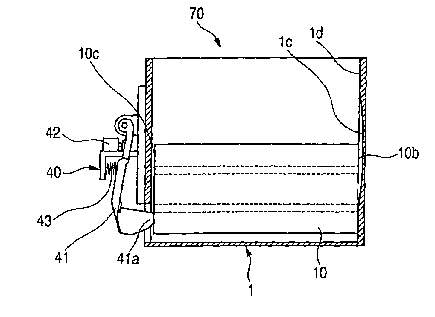
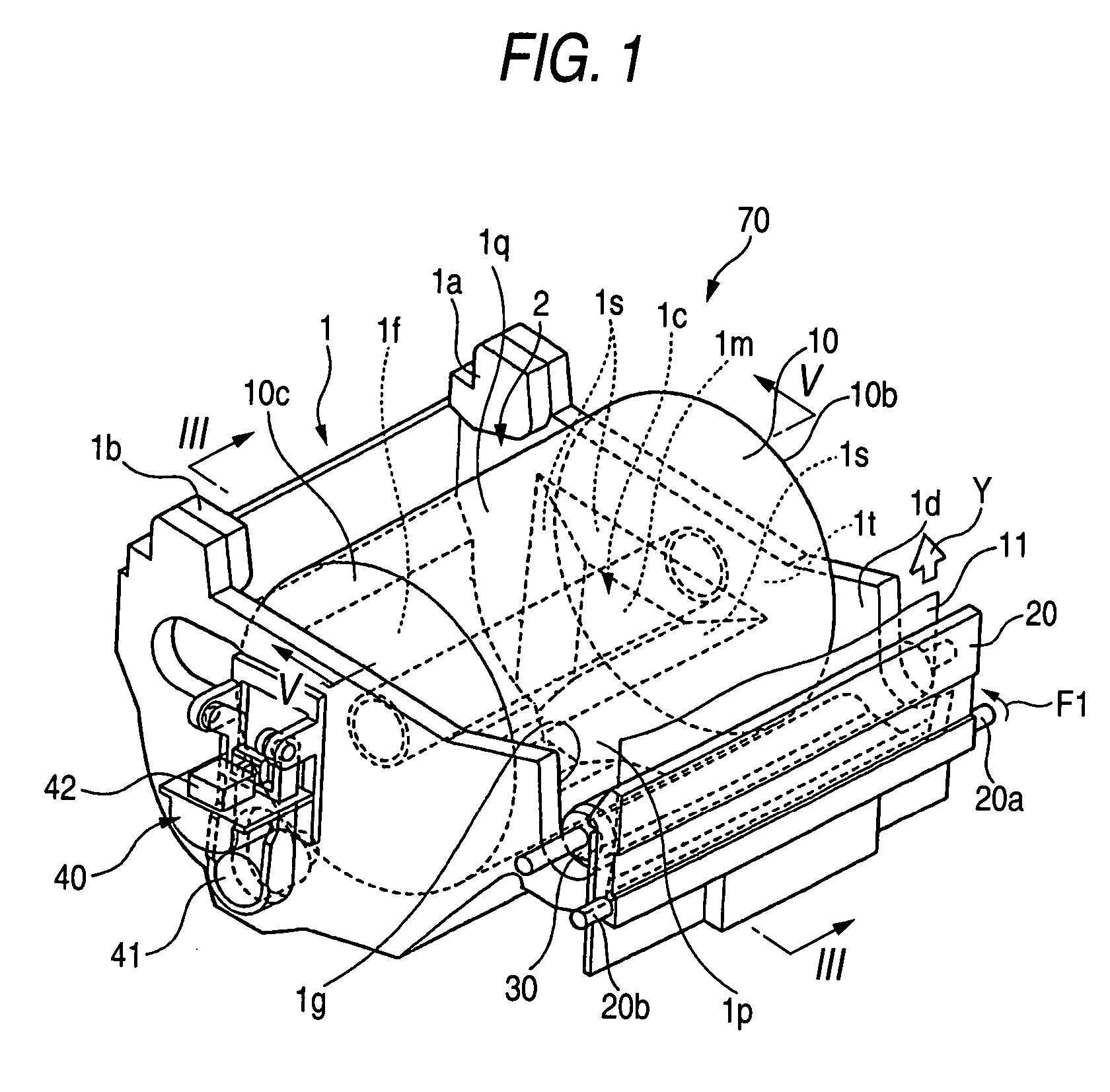
[0069]As shown in FIG. 1, the printer 70 comprises a rolled paper holder 1, a thermal recording head 20 disposed on one side (front side of the printer) of a paper storage space 2 of the rolled paper holder 1, a platen roller 30, and a near-end detector 40 for detecting that the remaining amount of the rolled paper 10 is coming to an end.

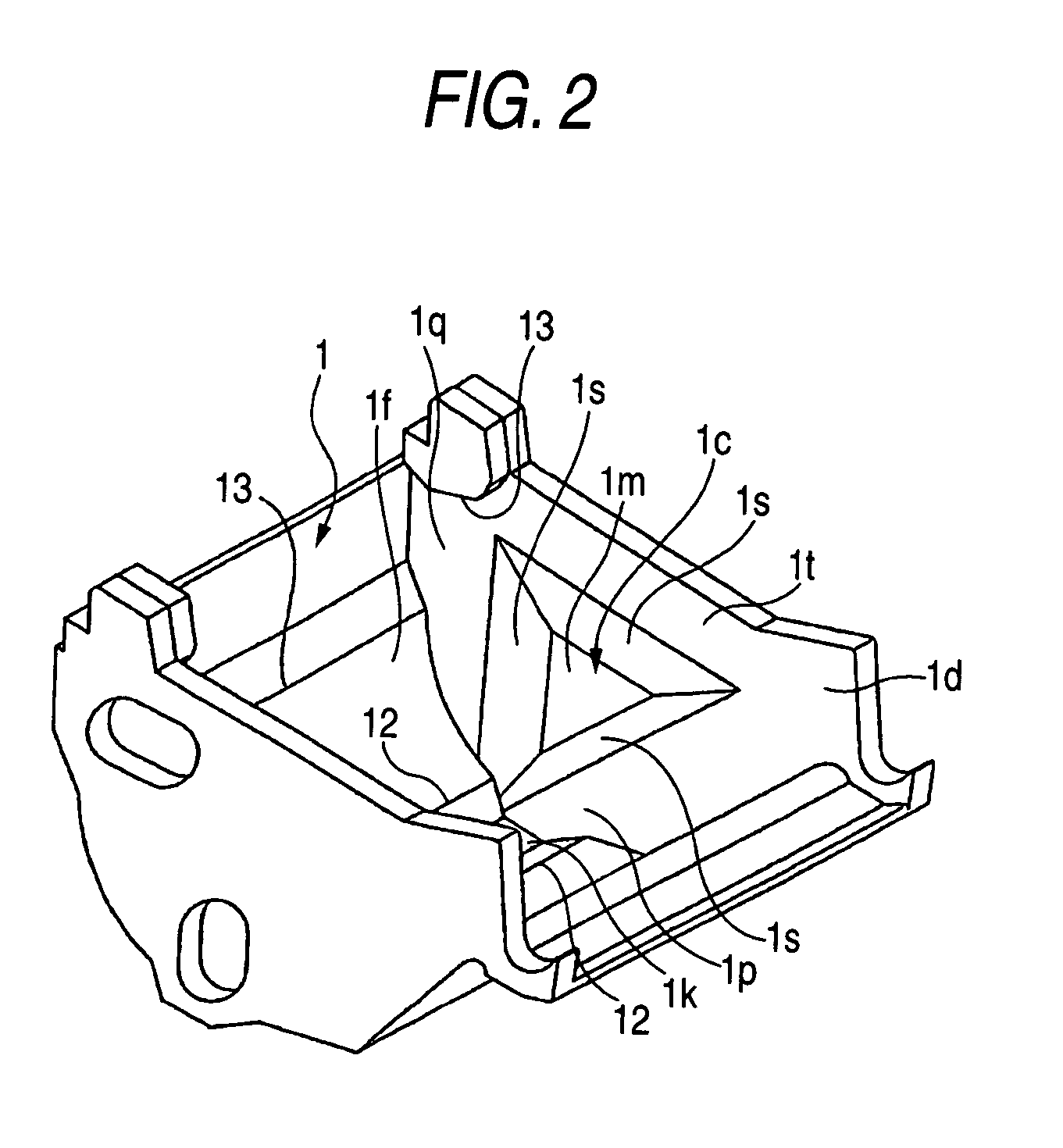
[0070]The rolled paper holder 1 includes a curved bottom face 1f for supporting the rolled paper ...


PUM

PropertyMeasurementUnit
mounting angleaaaaaaaaaa
diameteraaaaaaaaaa
sizeaaaaaaaaaa

Abstract

In a holder for holding a rolled recording medium, each of a pair of side wall members is opposed to a side end face of the rolled recording medium to regulate a position of the rolled recording medium in a widthwise direction thereof. At least one of the side wall members includes a first section adapted to be brought into contact with the side end face, and a second section adapted to avoid contact with the side end face. A position of the second section is determined such that an upper part of the side end face is free from contact with the at least one of the side wall members, and a position of the first section is determined such that a lower part of the side end face is brought into contact with the first section.

Description

BACKGROUND OF THE INVENTION[0001]The present invention relates to a rolled paper holder and a printer incorporating the same.[0002]A printer is known for forming images (including “character printing”) on a recording medium such as paper (hereinafter, referred as “recording paper”), using rolled paper as the recording paper. The rolled paper is advantageous in that it enables a continuous supply of the recording paper for a long time period.[0003]In the printer of this type, there are a shaft-supporting type and a throw-in type in connection with the structure of a paper feeding section for holding the rolled recording paper. In comparison with the shaft-supporting type, which employs such structure that the supporting shaft is inserted into the core hole of the rolled paper, the throw-in type is very convenient since the operation for setting the rolled recording paper is simply to put the rolled recording paper into a paper storage space.[0004]A first example of a related-art thro...

Claims


Application Information

Patent Timeline
Patent Type & Authority Patents(United States)
IPC IPC(8): B65H75/00B41J15/04B41J2/32B65H16/02B65H26/08G03G15/00
CPCB41J15/042B65H16/028B65H2301/41386B41J11/70G03G15/652
Inventor KOYABU, AKIRA
Owner SEIKO EPSON CORP
Why Eureka
Try Eureka