Vacuum preventing device of scroll compressor

a vacuum prevention and scroll compressor technology, which is applied in the direction of machines/engines, positive displacement liquid engines, liquid fuel engines, etc., can solve the problems of reducing affecting and the open and shut member b>17/b> is not smooth to operate, so as to reduce the clearance and increase the compression efficiency of the compressor.

Inactive Publication Date: 2006-03-28
LG ELECTRONICS INC
View PDF10 Cites 36 Cited by
  • Summary
  • Abstract
  • Description
  • Claims
  • Application Information

AI Technical Summary

Benefits of technology

[0029]Therefore, an object of the present invention is to provide a scroll compressor and a vacuum preventing device of the scroll compressor that are capable of heightening a compression efficiency of a compressor by minimizing a clearance between an upper surface of an open an

Problems solved by technology

In case of a pump down or an expansion valve clogging, the suction pressure zone (S1) of the compressor is in a high vacuum state, and at this time, a part of the compressor can be damaged.
The finer the clearance (t) is, the more effectively the gas is blocked but the open and shut member 17 is not smoothly operated.
With the increased clearance, the gas at the disc

Method used


Image

  • Vacuum preventing device of scroll compressor
  • Vacuum preventing device of scroll compressor
  • Vacuum preventing device of scroll compressor

Examples


first embodiment

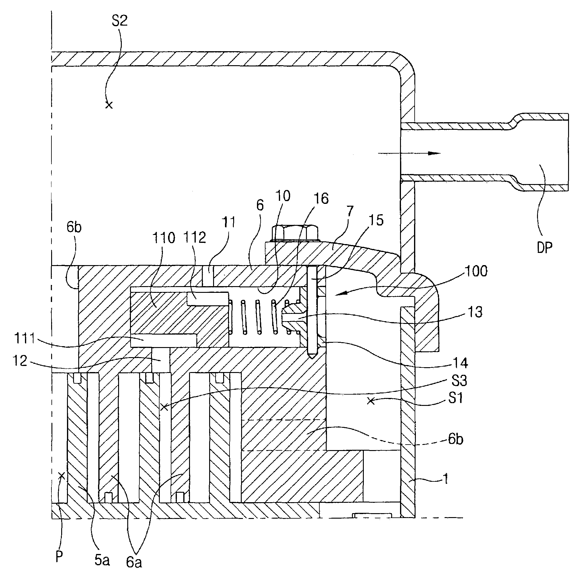
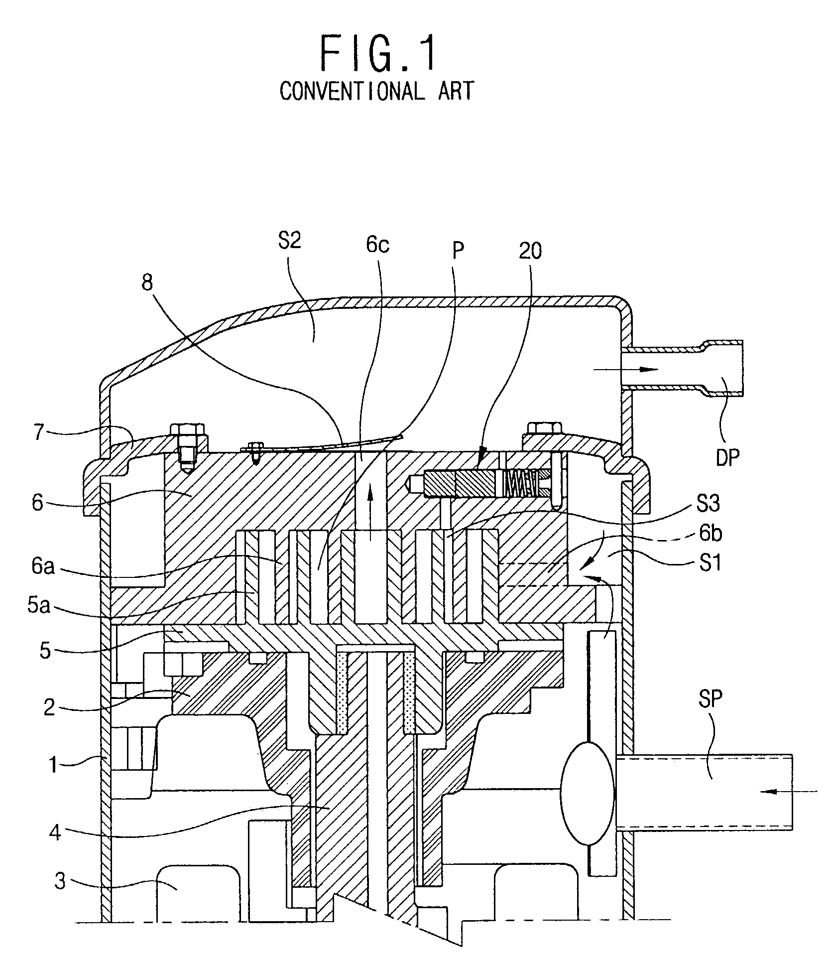
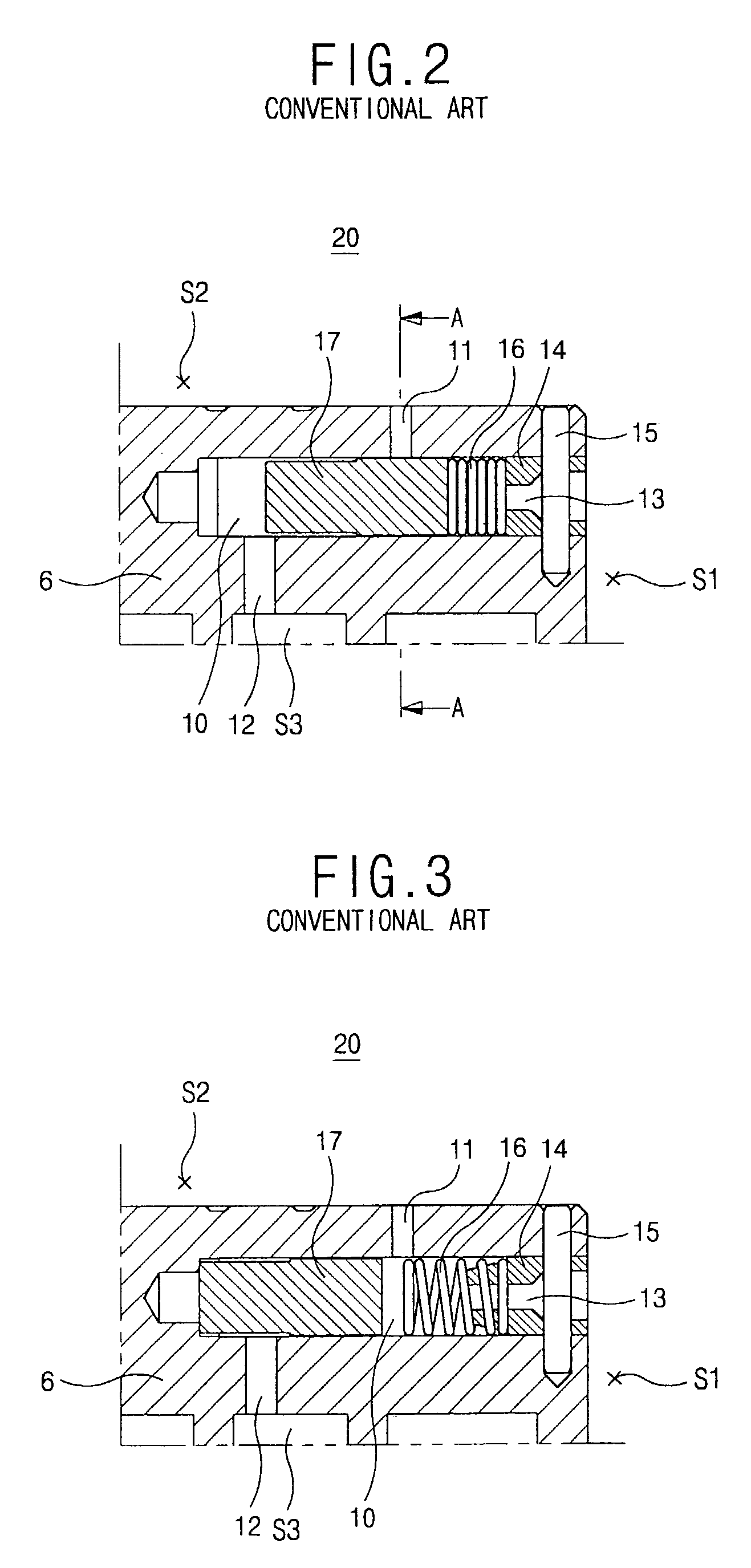
[0050]FIG. 5 is a vertical-sectional view showing a portion of a scroll compressor in accordance with the present invention, FIG. 6 is an exploded perspective view showing a vacuum preventing device of the scroll compressor of FIG. 5, FIG. 7 is a vertical-sectional view showing the operation of the vacuum preventing device when a compressor is normally operated, and FIG. 8 is a vertical-sectional view showing an operation of the vacuum preventing device when the compressor is not normally operated.

[0051]As shown in FIGS. 5 through 8, the scroll compressor includes a case 1 divided into a suction pressure zone (S1) for sucking a gas and a discharge pressure zone (S2) for discharging a gas; a fixed scroll 6 fixedly installed inside the case 1; an orbiting scroll 5 coupled to the fixed scroll 6 to form a compression space (P) communicating with an internal middle pressure zone (S3) and coupled to be movable eccentrically in an orbiting manner to the rotational shaft 4 of the drive moto...

second embodiment

[0077]FIG. 9 is an exploded perspective view of a scroll compressor in accordance with the present invention, and FIG. 10 is a vertical-sectional view showing an operation of a vacuum preventing device when the compressor of FIG. 9 is normally operated.

[0078]As shown in FIGS. 9 and 10, a vacuum preventing device 200 in accordance with the second embodiment of the present invention is constructed such that a tilting moment preventing protrusion 112b is formed at the bottom of the suction gas reception portion 112 and a discharge pressure hole 11 is positioned at the right center of the upper surface of the tilting moment preventing protrusion 112b when the compressor is normally operated.

[0079]In this manner, the resultant forces of the middle pressure applied to the lower portion of the open and shut member 110 and the discharge pressure applied to the upper portion of the open and shut member 110 work to the same vertical central line, thereby preventing the tilting moment of the o...

third embodiment

[0080]FIG. 11 is an exploded perspective view showing a vacuum preventing device of a scroll compressor in accordance with the present invention.

[0081]As illustrated, a vacuum preventing device 300 in accordance with the third embodiment of the present invention includes a guide groove 121 and a guide rail 120 which are generally used at an inner wall of the chamber 10 and an outer surface of the open and shut member 110, respectively, in order to prevent a smooth sliding movement of the open and shut member 110 and the tilting moment.

[0082]In this respect, conversely, the guide rail 120 can be installed at the inner wall of the chamber 10 and the guide groove 121 can be installed at the outer surface of the open and shut member 110.


PUM


Abstract

A vacuum preventing device of a scroll compressor includes: a chamber formed at one side of a fixed scroll and having a suction pressure hole, a middle pressure hole and a discharge pressure hole communicating with a suction pressure zone, a middle pressure zone and a discharge pressure zone, each formed at a certain portion of an inner circumferential surface; an open and shut member installed inside the chamber and selectively communicating the discharge pressure hole and the suction pressure hole by virtue of a gas pressure of the middle pressure zone and an elastic force of a spring; and a gas leakage preventing unit for preventing a gas leakage in a normal operation by reducing a clearance between an inner wall of the chamber positioned at the side of the discharge pressure hole and the open and shut member.

Description

BACKGROUND OF THE INVENTION[0001]1. Field of the Invention[0002]The present invention relates to a scroll compressor and a vacuum preventing device of the scroll compressor, and more particularly, to a scroll compressor and a vacuum preventing device of the scroll compressor that are capable of preventing a compressor from being vacuumized by flowing back a gas at the side of a discharge pressure toward the side of a suction pressure in occurrence of an abnormal operation such as a pump-down or an expansion valve clogging.[0003]2. Description of the Background Art[0004]In general, a compressor, changing a mechanical energy to a latent energy of a compressive fluid, is divided into a reciprocating type, a scroll type, a centrifugal type and a vane type.[0005]Among them, the scroll type compressor has a structure of sucking, compressing and discharging gas by using a rotor like the centrifugal type compressor or the vane type compressor, unlike the reciprocating type compressor which ...

Claims


Application Information

Patent Timeline
IPC IPC(8): F04B49/00F01C1/02F01C21/00F04B17/00F04C18/02F04C23/00F04C28/26F04C28/28
CPCF04C18/0215F04C28/28F04C28/26F04C23/008F04C2270/72F04C18/02
Inventor KOO, IN-HWE
Owner LG ELECTRONICS INC
Why Eureka
Try Eureka