Image-taking apparatus and monitoring system

a technology which is applied in the field of image-taking apparatus and monitoring system, can solve the problems of not being able to determine from positional information, not being able to provide knowledge about the circumstances surrounding the person to be assisted, and being unsuitable for use by a lost child (especially an infant) or a wandering elderly person, and achieves the effect of convenient us

Active Publication Date: 2006-03-28
CANON KK
View PDF7 Cites 46 Cited by
  • Summary
  • Abstract
  • Description
  • Claims
  • Application Information

AI Technical Summary

Benefits of technology

[0013]It is an object of the present invention to provide an image-taking apparatus which is easy to use and is capable of a search for a person or walking support, and a monitoring system which uses the image-taking apparatus.

Problems solved by technology

Only the use of the GPS or the like to take positional information, however, cannot provide knowledge about circumstances surrounding the person to be aided.
Specifically, the aforementioned service has a problem that it is not possible to determine from the positional information on a map whether or not the person to be aided is in a situation in which he / she needs emergent help or whether or not he / she is at a position which can be easily found.
Thus, it is not suitable for use by a lost child (especially an infant) or a wandering elderly person.
In Embodiment 2, the handling of the cable is cumbersome when the video camera is hung from his / her neck.
Especially for an infant, the video camera and the cable hung from his / her neck interfere with the movement of his / her body, so that he / she may take off the video camera from his / her body or disconnect the cable to make normal operation of the system impossible.
As shown in FIG. 10, however, such a super wide-angle lens 1000 is formed of as much as 8 lens units, and thus very heavy and considerably large in lens length.
As a result, the system proposed in the aforementioned patent is likely to be inappropriate for actual use.

Method used


Image

  • Image-taking apparatus and monitoring system
  • Image-taking apparatus and monitoring system
  • Image-taking apparatus and monitoring system

Examples


embodiment 1

[0028](Embodiment 1)

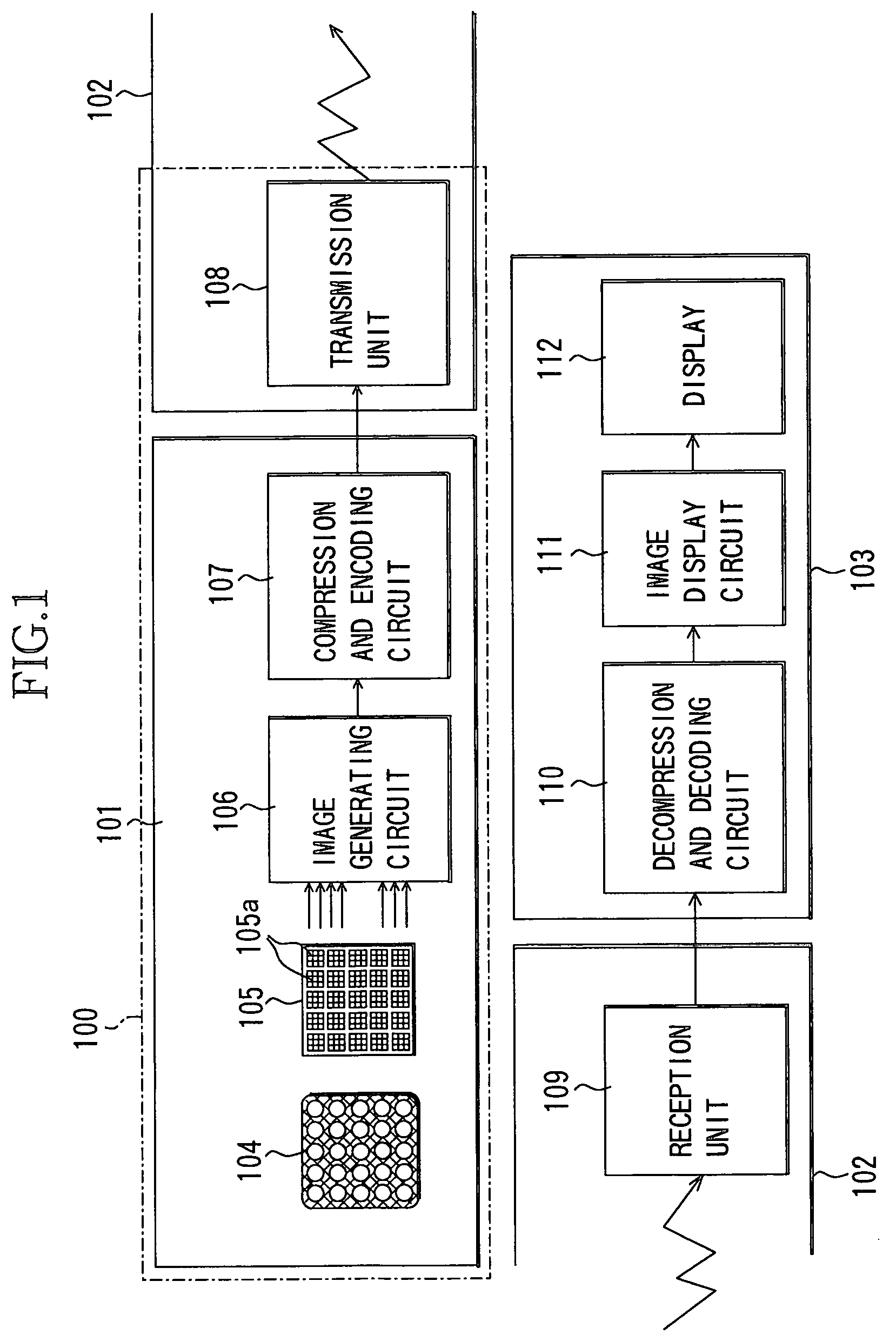
[0029]FIG. 1 is a block diagram showing the structure of a remote monitoring system which is Embodiment 1 of the present invention.

[0030]The remote monitoring system of Embodiment 1 employs an image-taking apparatus 100 having a compound eye image-pickup unit 101 which uses a compound eye optical device to take image at a wide field angle and a transmission unit 108.

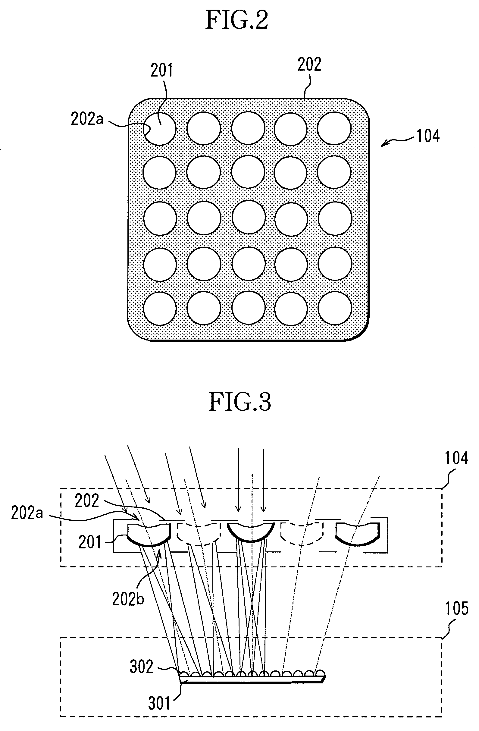
[0031]The compound eye image-pickup unit 101 has a compound eye optical unit 104 which has a plurality of lenses arranged so as to juxtapose to each other in a matrix-like form. Each of the lenses faces to an object (not shown) and has an action of forming luminous flux from the object into an image. The compound eye image-pickup unit 101 also has an image-pickup device 105 as a photoelectrical conversion element which photoelectrically converts an object image formed by each lens of the compound eye optical unit 104. The unit 101 also has an image generating circuit 106 which produces a digital image...

embodiment 2

[0067](Embodiment 2)

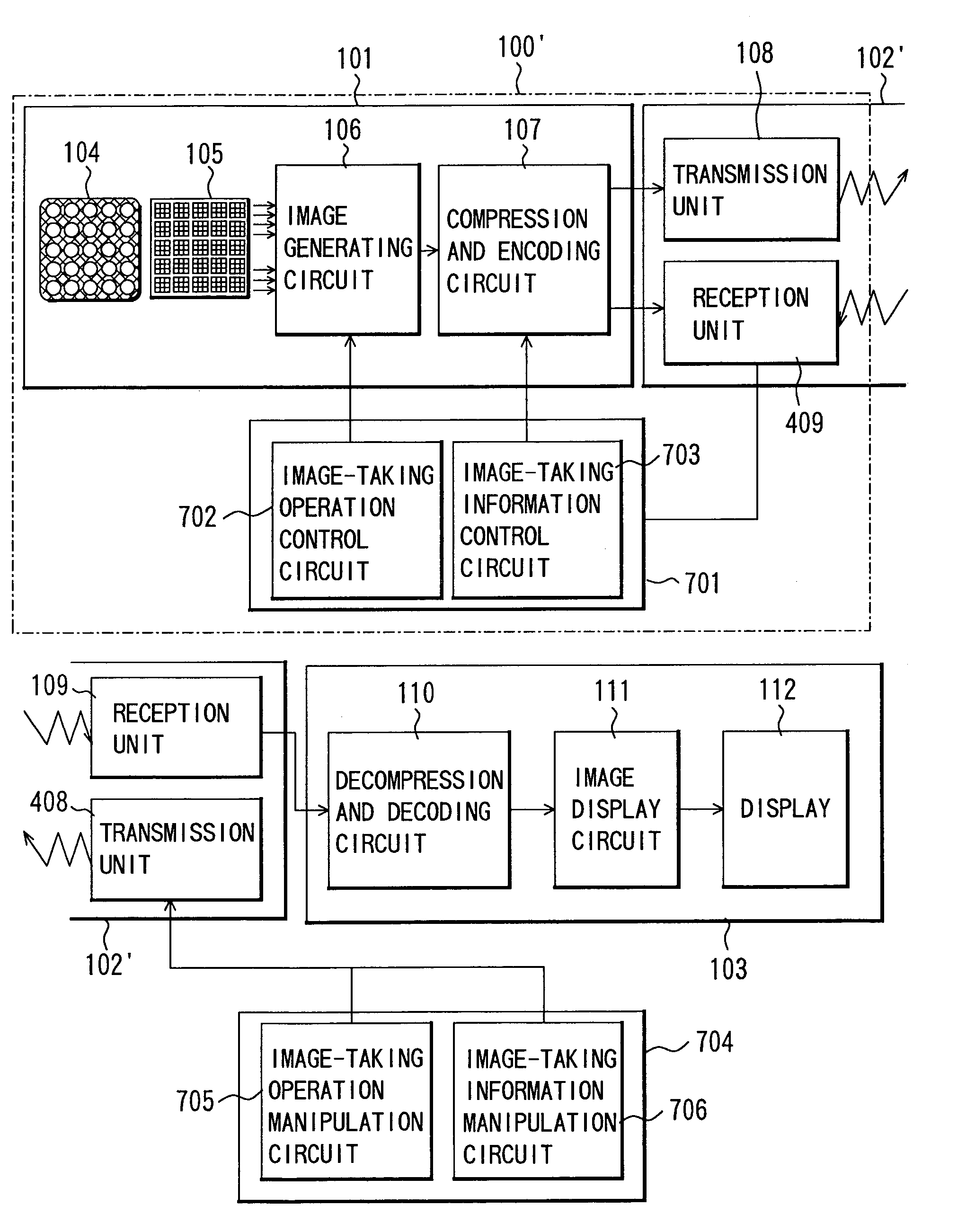
[0068]FIG. 7 shows the structure of a remote monitoring system which is Embodiment 2 of the present invention. It should be noted that, in Embodiment 2, components identical to those in Embodiment 1 are designated with the same reference numerals as those in Embodiment 1 to omit description thereof.

[0069]An image-taking apparatus 100′ used in the system of Embodiment 2 has an image-taking control circuit 701, later described, added to the image-taking apparatus 100 described in Embodiment 1 and also has a manipulation apparatus 704 on the side of a monitor apparatus 103. In addition, in a communication system 102′, a reception unit 409 is added to the side of the image-taking apparatus 100′ and a transmission unit 408 is added to the side of the monitor apparatus 103 in the communication system of Embodiment 1.

[0070]The image-pickup control circuit 701 on the side of the image-taking apparatus 100′ is formed of an image-taking operation control circuit 702 which ...

embodiment 3

[0081](Embodiment 3)

[0082]FIGS. 8(A) and (B) show the structure of an image-taking apparatus which is Embodiment 3 of the present invention. FIG. 9 shows the structure of a remote monitoring system which has the image-taking apparatus 100″. The image-taking apparatus 100″ of the embodiment has a voice input / output unit 901 including a microphone 902 and a speaker 903 added to the image-taking apparatus 100 described in Embodiment 1, and also has a voice input / output unit 911 including a microphone 912 and a speaker 913 on the side of the monitor apparatus 103 described in Embodiment 1. A communication system 102′ is identical to the counterpart described in Embodiment 2. In Embodiment 3, components identical to those in Embodiments 1 and 2 are designated with the same reference numerals as those in Embodiments 1 and 2 to omit description thereof.

[0083]FIGS. 8(A) and 8(B) show the structures of the front surface and the back surface of the image-taking apparatus 100″ formed in a badg...


PUM


Abstract

An image-taking apparatus is disclosed which is easy to use and is capable of a search for a person or walking support without fail. The image-taking apparatus comprises a compound eye optical unit, an image-pickup device which photoelectrically converts an object image formed by the compound eye optical unit, and a transmission unit which transmits image information provided by using the image-pickup device. The compound eye optical unit and the image-pickup device are held by a hold member which is provided with an attachment member for attachment to a user.

Description

BACKGROUND OF THE INVENTION[0001]1. Field of the Invention[0002]The present invention relates to an image-taking apparatus which uses an image-pickup device to take image information and to a monitoring system which uses the image-taking apparatus.[0003]2. Description of Related Art[0004]Locating service which uses the GPS (Global Positioning System) has been provided as aid service for lost children, wandering demented elderly people, and visually handicapped people.[0005]This is service in which a person to be aided such as a child or an elderly person carries a GPS terminal (such as a dedicated terminal or a cellular phone having a GPS function) and the current position of the person is determined on the basis of the positions of GPS satellites and the time to rescue him / her.[0006]Only the use of the GPS or the like to take positional information, however, cannot provide knowledge about circumstances surrounding the person to be aided. Specifically, the aforementioned service has...

Claims


Application Information

Patent Timeline
Patent Type & Authority Patents(United States)
IPC IPC(8): G08G1/017H04N7/18H04N5/225
CPCH04N7/183H04N5/2254H04N23/661H04N23/50H04N23/63
Inventor KAWAI, TAKASHI
Owner CANON KK
Why Eureka
Try Eureka