Optical mouse adapted for use on glass surfaces

a mouse and glass surface technology, applied in the field of optical mouse, can solve the problems of awkward cleaning operation, less attractive devices, and optical mouse type not working properly on glass-covered surfaces

Inactive Publication Date: 2006-03-28
AVAGO TECH WIRELESS IP SINGAPORE PTE
View PDF3 Cites 50 Cited by
  • Summary
  • Abstract
  • Description
  • Claims
  • Application Information

AI Technical Summary

Problems solved by technology

Unfortunately, the ball picks up grease and other dirt from the surface and transfers this material to the cylinders.
The resulting coating on the cylinders interferes with the motion of the cylinders, and hence, the devices must be cleaned periodically.
The cleaning operation is awkward and time consuming.
The need to use this special pad made these devices less attractive than the mechanical mice discussed above.
Unfortunately, this type of optical mouse does not function properly on a glass-covered surface such as the glass tops used on many desks or other work surfaces.
Hence, optical mice have not been useable on many glass covered desktops.

Method used


Image

  • Optical mouse adapted for use on glass surfaces
  • Optical mouse adapted for use on glass surfaces
  • Optical mouse adapted for use on glass surfaces

Examples


Embodiment Construction

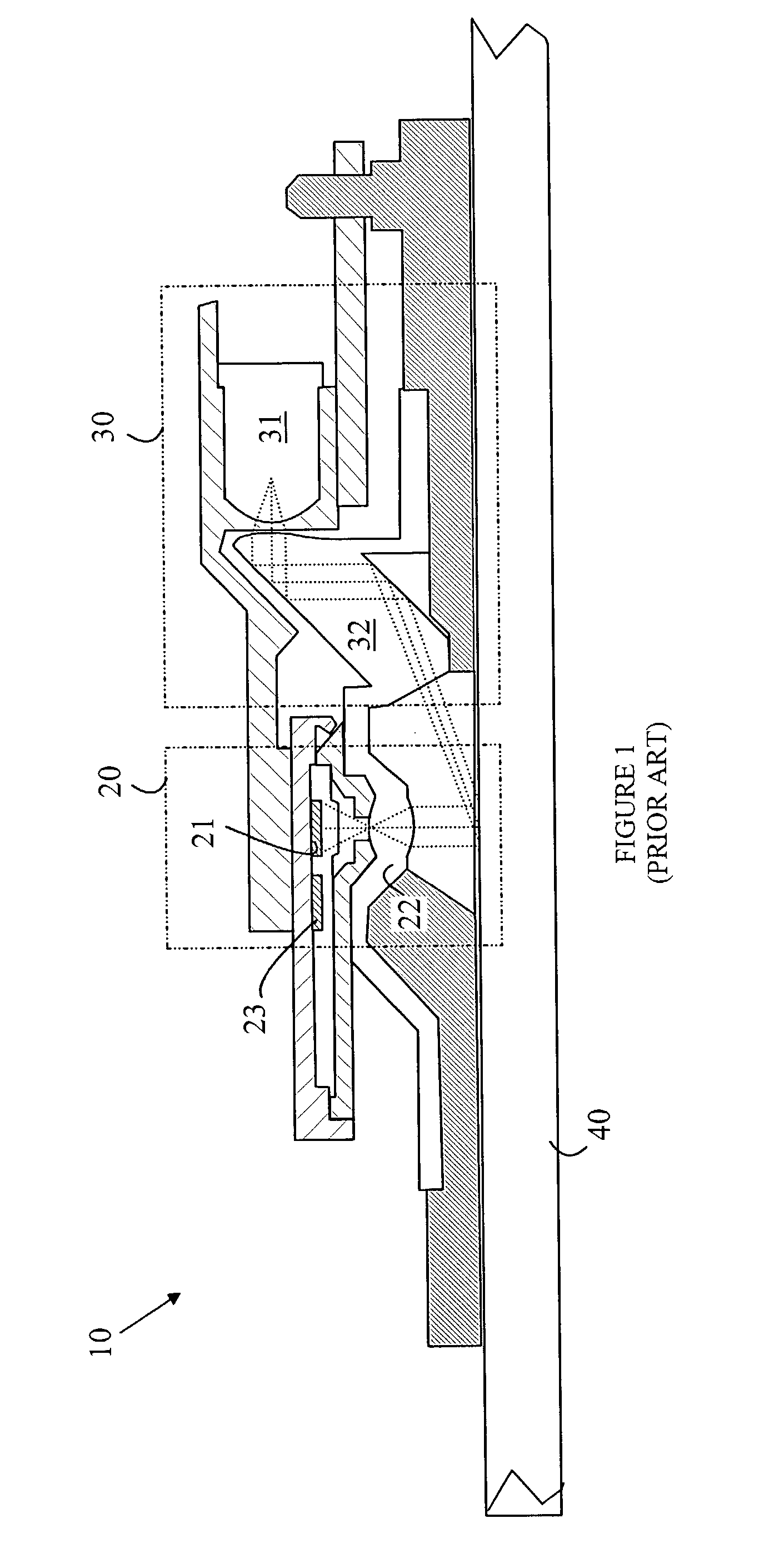
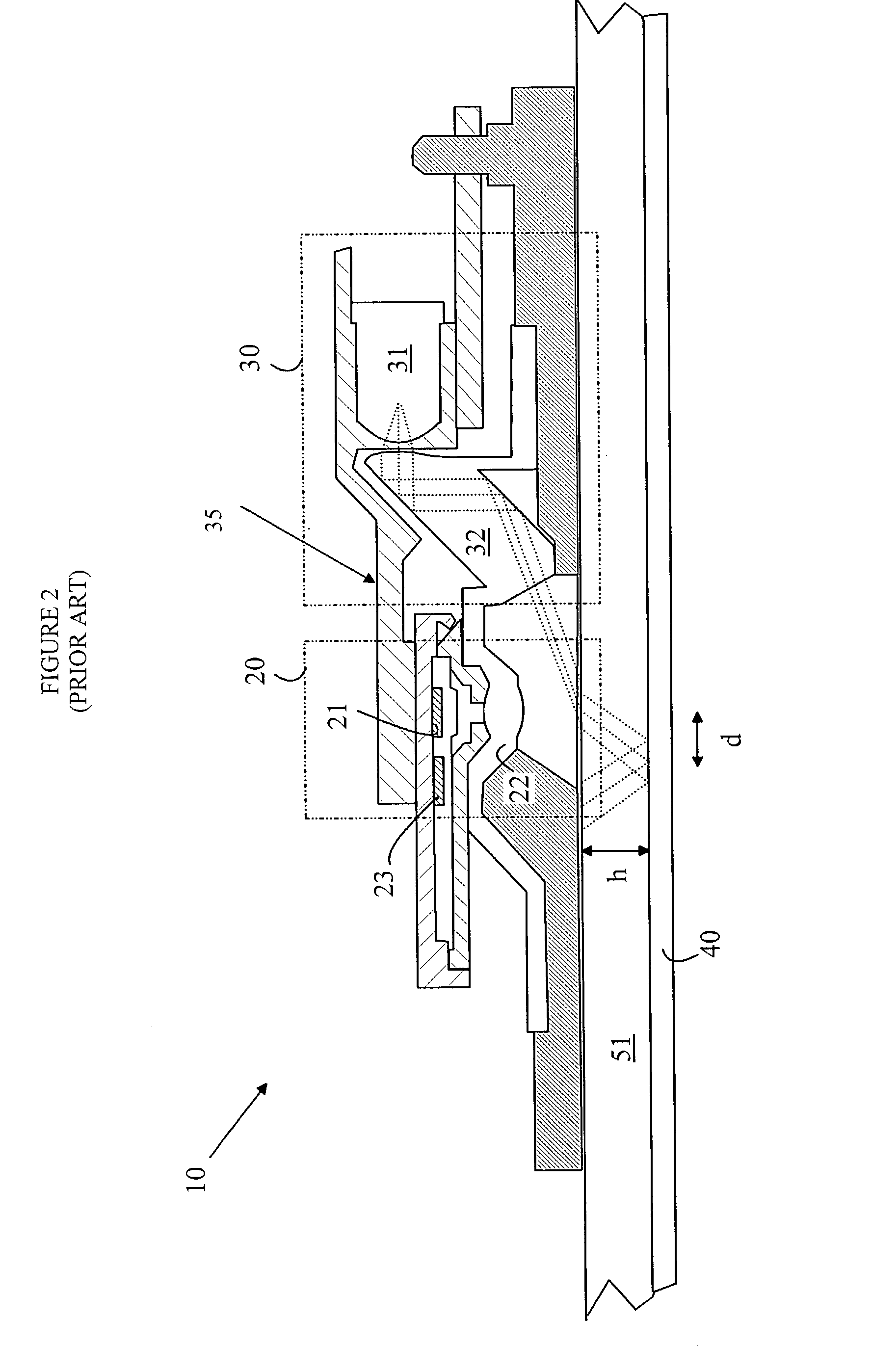
[0011]The manner in which the present invention provides its advantages can be more easily understood with reference to FIGS. 1 and 2. FIG. 1 is a simplified cross-sectional view of an optical mouse 10 that moves over an opaque substrate 40. Mouse 10 may be viewed as having two principal components, an illumination section 30 and an imaging section 20. Illumination section 30 typically includes an LED light source 31 and an optical assembly 32 that illuminates surface 40 with collimated light that strikes the surface at a shallow angle relative to the surface. Light from the illuminated portion of the surface is imaged by the imaging section onto a sensor 21 with the aid of a lens assembly 22. Sensor 21 is a two-dimensional array of imaging elements that forms an image of a portion of surface 40.

[0012]When the mouse is moved relative to the surface, the image shifts on sensor21. If images are taken sufficiently close together in time, each successive image will contain a portion of ...


PUM


Abstract

A pointing device having an illumination system, camera system, and positioning mechanism is disclosed. The illumination system illuminates a surface below a transparent plate having a constant thickness. The camera system records images of the illuminated surface. The positioning mechanism adjusts the relative position of the illumination with respect to the camera system. The relative position is determined by the constant thickness. The positioning mechanism has a first position corresponding to a predetermined value for the constant thickness and a second position corresponding to the constant thickness being zero. The positioning mechanism is operable by a user of the pointing device to compensate for different thicknesses of transparent plates.

Description

FIELD OF THE INVENTION[0001]The present invention relates to computer pointing devices, and more particularly, to an improved optical mouse.BACKGROUND OF THE INVENTION[0002]A common form of pointing device for use with computers and the like is referred to as a “mouse”. The computer user moves the device over a surface to move a cursor on the computer screen. The amount of motion and the direction of motion of the mouse are sensed by the device and determine the distance and direction in which the cursor moves on the screen. Inexpensive mice based on a ball that rolls over the surface have been used for some time. The ball turns two cylinders that sense the distance and direction of motion. Unfortunately, the ball picks up grease and other dirt from the surface and transfers this material to the cylinders. The resulting coating on the cylinders interferes with the motion of the cylinders, and hence, the devices must be cleaned periodically. The cleaning operation is awkward and time...

Claims


Application Information

Patent Timeline
Patent Type & Authority Patents(United States)
IPC IPC(8): G09G5/08G06F3/03G06F3/033
CPCG06F3/03543G06F3/0317
Inventor KOAY, BAN KUAN
Owner AVAGO TECH WIRELESS IP SINGAPORE PTE
Why Eureka
Try Eureka