System and method for detecting objects in images

a detection system and object technology, applied in the field of computer vision and pattern recognition, can solve the problems of low camera quality, poor lighting of a scene, and difficult face detection,

Active Publication Date: 2006-03-28
MITSUBISHI ELECTRIC RES LAB INC
View PDF4 Cites 217 Cited by
  • Summary
  • Abstract
  • Description
  • Claims
  • Application Information

AI Technical Summary

Problems solved by technology

Of all of the applications where computer vision is used, face detection presents an extremely difficult challenge.
For example, in images acquired by surveillance cameras, the lighting of a scene is usually poor and uncontrollable, and the cameras are of low quality and usually distant from potentially important parts of the scene.
Significant events are unpredictable.
In other words, the images to be analyzed are substantially unconstrained.
Moreover, in most images that do include a face, the amount of the image that is a face is also very small.
As a disadvantage, the features used by their method are limited to linear projections and upper and lower thresholds.
In addition, because the classifier is a conjunction of linear projections followed by a threshold, the resulting classification function is limited to a convex region in the input space, which is a strong limitation that makes their system a weak classifier.
However, there are several problems with their cascaded approach.
This degrades performance when the distribution of acceptable and rejected examples are substantially equal.
Another disadvantage of their method is that later stages of the cascade ignore detailed information that was available during earlier stages of the cascade.
Another disadvantage is their mechanism for setting the rejection thresholds.
Therefore, in the early stages, one must be very conservative and not discard a potentially correct patch.
Their process does not distinguish example patches that are easy to classify, and are eventually classified correctly, and those example patches, which are very difficult to classify and are eventually misclassified.
This results in rejection thresholds which are lower and less effective in reducing processing time.

Method used


Image

  • System and method for detecting objects in images
  • System and method for detecting objects in images
  • System and method for detecting objects in images

Examples


Embodiment Construction

Overview of System Structure and Operation

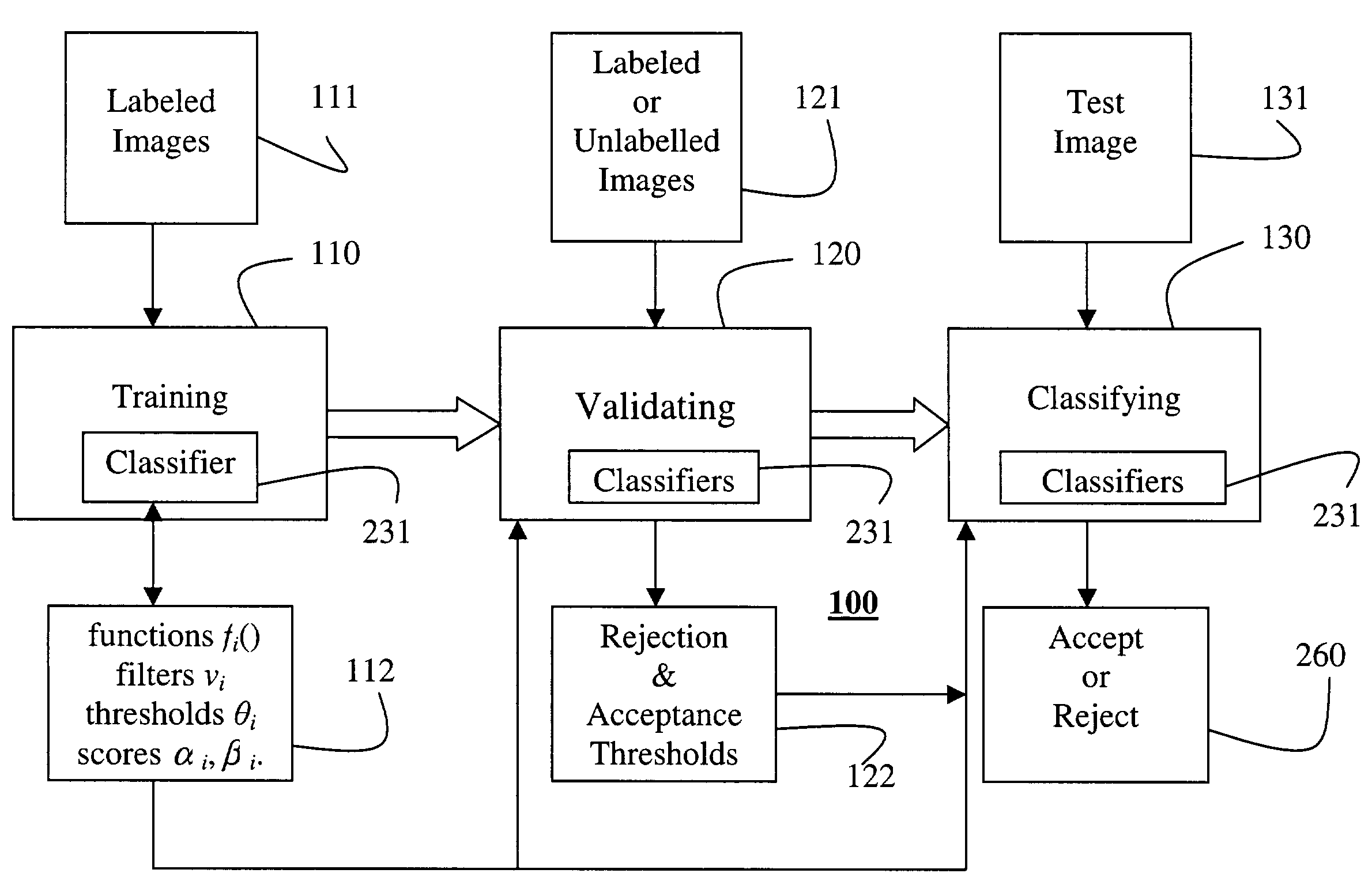
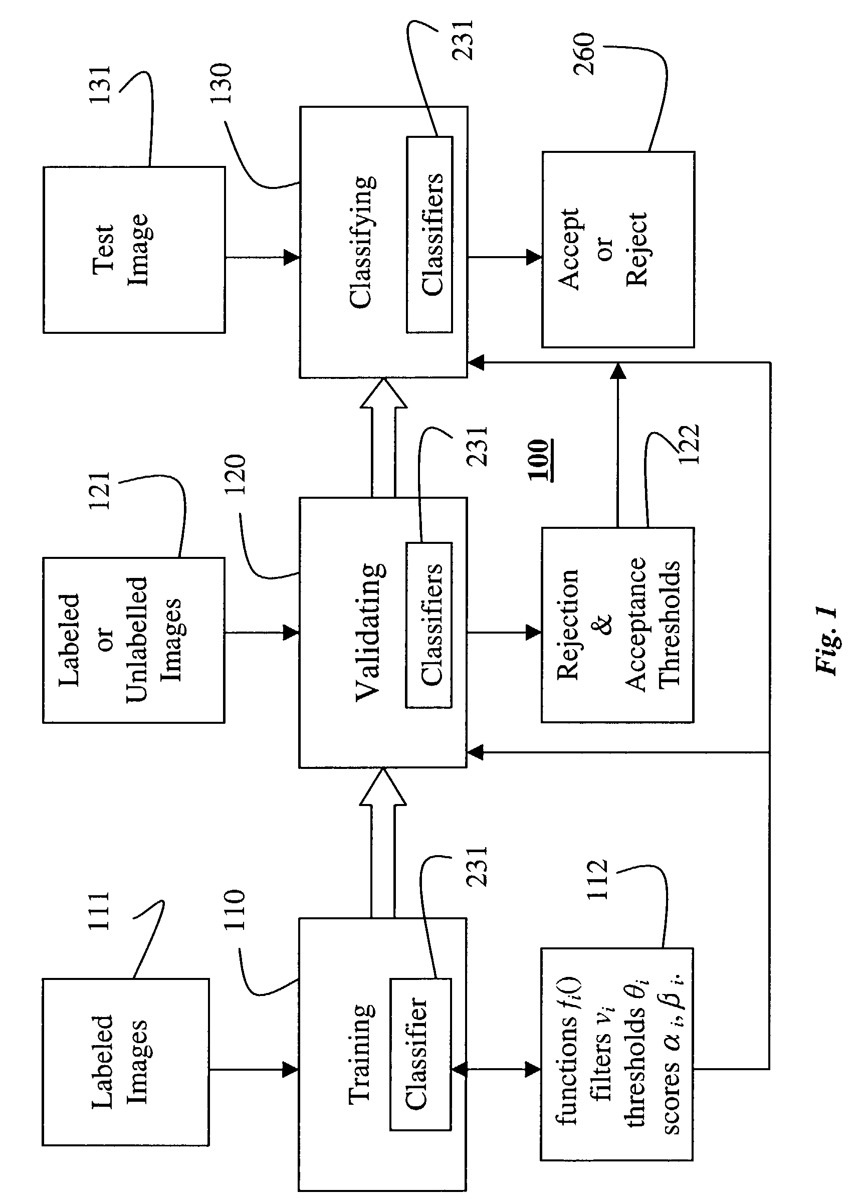
[0022]FIG. 1 shows a system and method 100 for detecting objects in images according to the invention. In one application, the objects detected in the images are faces, however, it should be understood that other objects can also be detected. The system 100 includes three fundamental phases, training 110, validating 120, and classifying 130.

[0023]The training phase 110 takes as input a first set of labeled images 111. The nature of what is labeled in the images 111 determines what objects are detected. The labeled images 110 are processed to produce classifiers 231. As described in greater detail below, the processing uses a machine learning process to find an optimal set of parameters 112 for the classifiers 231.

[0024]The parameters 112 includes a sum of features. A feature is a function ƒi( ) of a filter νi applied to an image patch i and then compared to comparison threshold θi to yield either an acceptance score αi or a rejection score β...


PUM


Abstract

A method detects an object, such a face, in an image. The image is first partitioned into patches of various sizes using either an integral image or a Gaussian pyramid. Features in each patch are evaluated to determine a cumulative score. The evaluating is repeated while the cumulative score is within a range of an acceptance threshold and a rejection threshold, and otherwise the image is rejected when the accumulated score is less than the rejection threshold and accepted as including the object when the cumulative score is greater than the acceptance threshold.

Description

FIELD OF THE INVENTION[0001]This invention relates generally to the field of computer vision and pattern recognition, and more particularly to detecting objects such as faces in images.BACKGROUND OF THE INVENTION[0002]Of all of the applications where computer vision is used, face detection presents an extremely difficult challenge. For example, in images acquired by surveillance cameras, the lighting of a scene is usually poor and uncontrollable, and the cameras are of low quality and usually distant from potentially important parts of the scene. Significant events are unpredictable. Often, a significant event is people entering a scene. People are typically identified by their faces. The location and orientation of the faces in the scene are usually not controlled. In other words, the images to be analyzed are substantially unconstrained.[0003]In applications where a large number of images are to be analyzed, or the analysis needs to be performed in real-time, the number of images ...

Claims


Application Information

Patent Timeline
Patent Type & Authority Patents(United States)
IPC IPC(8): G06K9/62G06K9/00G06T7/00
CPCG06K9/00228G06V40/161
Inventor VIOLA, PAUL A.JONES, MICHAEL J.
Owner MITSUBISHI ELECTRIC RES LAB INC
Why Eureka
Try Eureka