

Collection of sludge from the floor of a basin with multiple balanced-flow headers
- Summary
- Abstract
- Description
- Claims
- Application Information
AI Technical Summary
Benefits of technology
Problems solved by technology
Method used
Image

Examples
Embodiment Construction
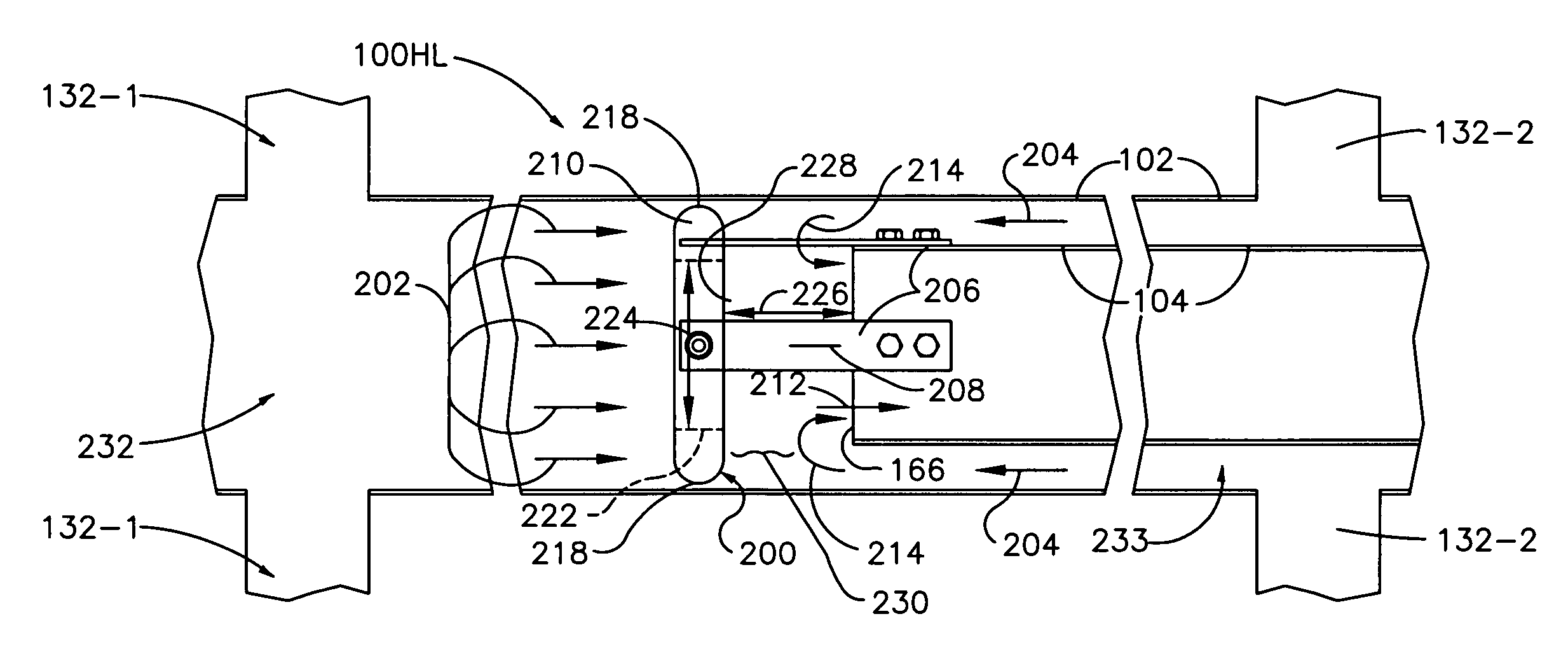
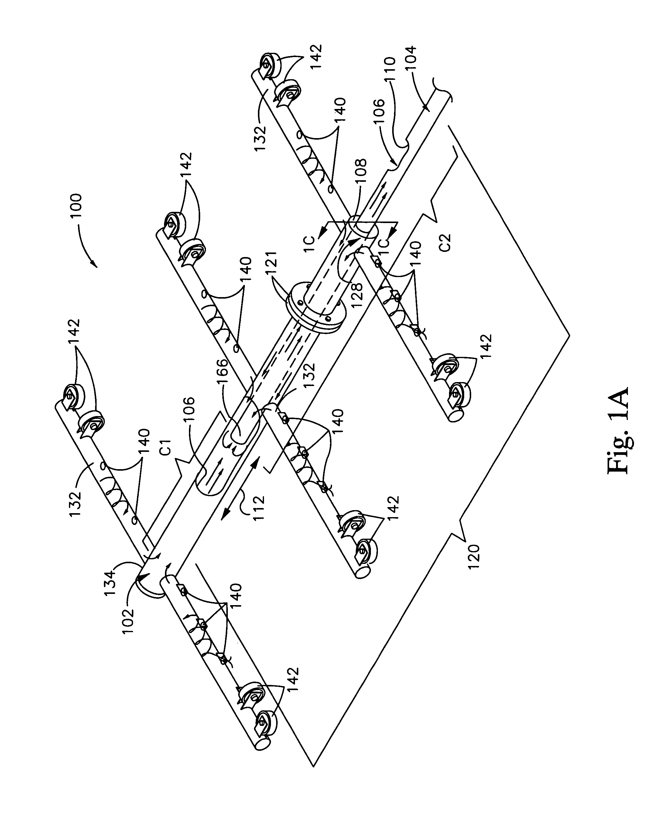
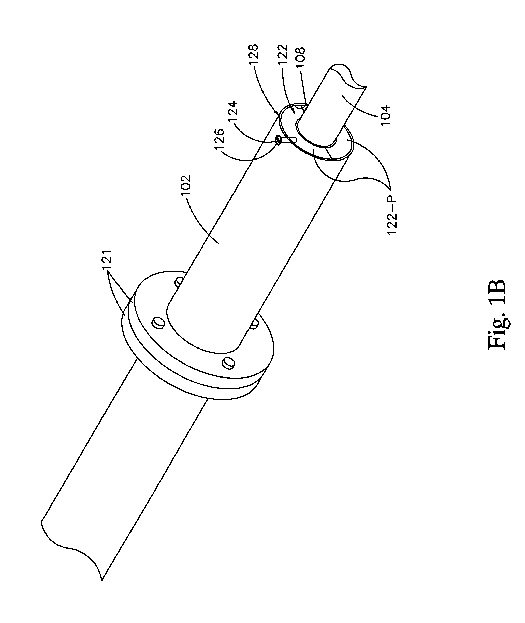
[0031]An invention is described for significantly increasing the flow rate through header pipes that collect sludge and liquid from the bottom of a basin, without causing the above-described problems in priming a sludge collection system, while balancing flows from separate headers that collect the sludge and liquid from the bottom. Telescopic pipe structures provide a way of achieving such sludge collection, while having an easily primed collection system, and providing the entire sludge collecting system in a low-clearance space under the settler and flocculating equipment that extends down near the bottom of the basin, wherein an inner pipe of the pipe structures carries a flow controller to achieve the balancing.
[0032]In the following description, numerous specific details are set forth in order to provide a thorough understanding of the present invention. It will be understood, however, to one skilled in the art, that the present invention may be practiced without some or all o...
PUM
| Property | Measurement | Unit |
|---|---|---|
| Flow rate | aaaaa | aaaaa |
| Area | aaaaa | aaaaa |
| Distance | aaaaa | aaaaa |
Abstract
Description
Claims
Application Information