Dual use decorating device

a dispenser and dual-use technology, applied in the field of hand-held dispensers, can solve the problems of bakers avoiding decorating their own deserts, collapsing cones, time-consuming and messy process,

Inactive Publication Date: 2006-04-04
WILTON INDS +1
View PDF25 Cites 35 Cited by
  • Summary
  • Abstract
  • Description
  • Claims
  • Application Information

AI Technical Summary

Benefits of technology

[0012]The present invention is directed to a container for dispensing a viscous fluid. The container includes an opening and a nozzle disposed within the opening. The nozzle has a sealed tip that extends outward from the opening in the container. A cap is secured to the nozzle. The cap has an opening therethrough. To use the container, the tip of the nozzle is cut to enable the viscous fluid to dispense therefrom at a first thickness. Additionally, when the cap is secured to the nozzle with the cut tip, the opening of the cap enables the viscous fluid to dispense therefrom at a second thickness less than the first thickness.

Problems solved by technology

The collapsible cones, however, may rupture or tear so as to leave the device inoperable.
Often, bakers avoid decorating their own deserts because of the trouble involved in making the decorating frosting in the small quantities and different colors desired.
In addition, once the icing is made, it must be loaded into either the cone or the bulb-shaped container which may be a time-consuming and messy process.
A disadvantage of such an arrangement, however, is that the user only has a single option with regard to the aperture size or shape through which the icing is dispensed.
This increases packaging cost and the user may lose the nozzle when storing the product.
Unless the container is resealed, the cap is also a useless or wasted component once the container is opened.
Once again, however, such an arrangement only provides the user with a single option in terms of an opening size and shape through which to dispense the icing.
In addition, such an arrangement is not suitable for packaging pre-made icing as the cap could become dislodged from the nozzle.
This would compromise the package sealing.
This arrangement, however, also only provides a single decorative opening and multiple pieces are required to install the nozzle.
The cap also becomes a useless piece that is discarded after the package is opened.

Method used


Image

  • Dual use decorating device
  • Dual use decorating device
  • Dual use decorating device

Examples


Embodiment Construction

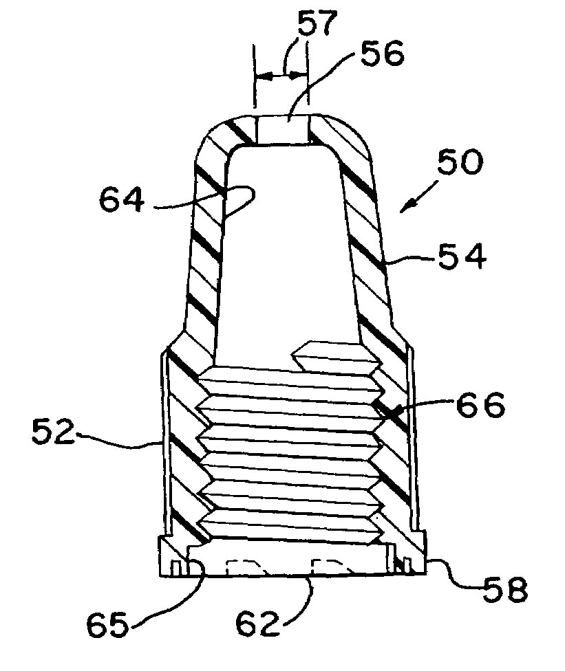
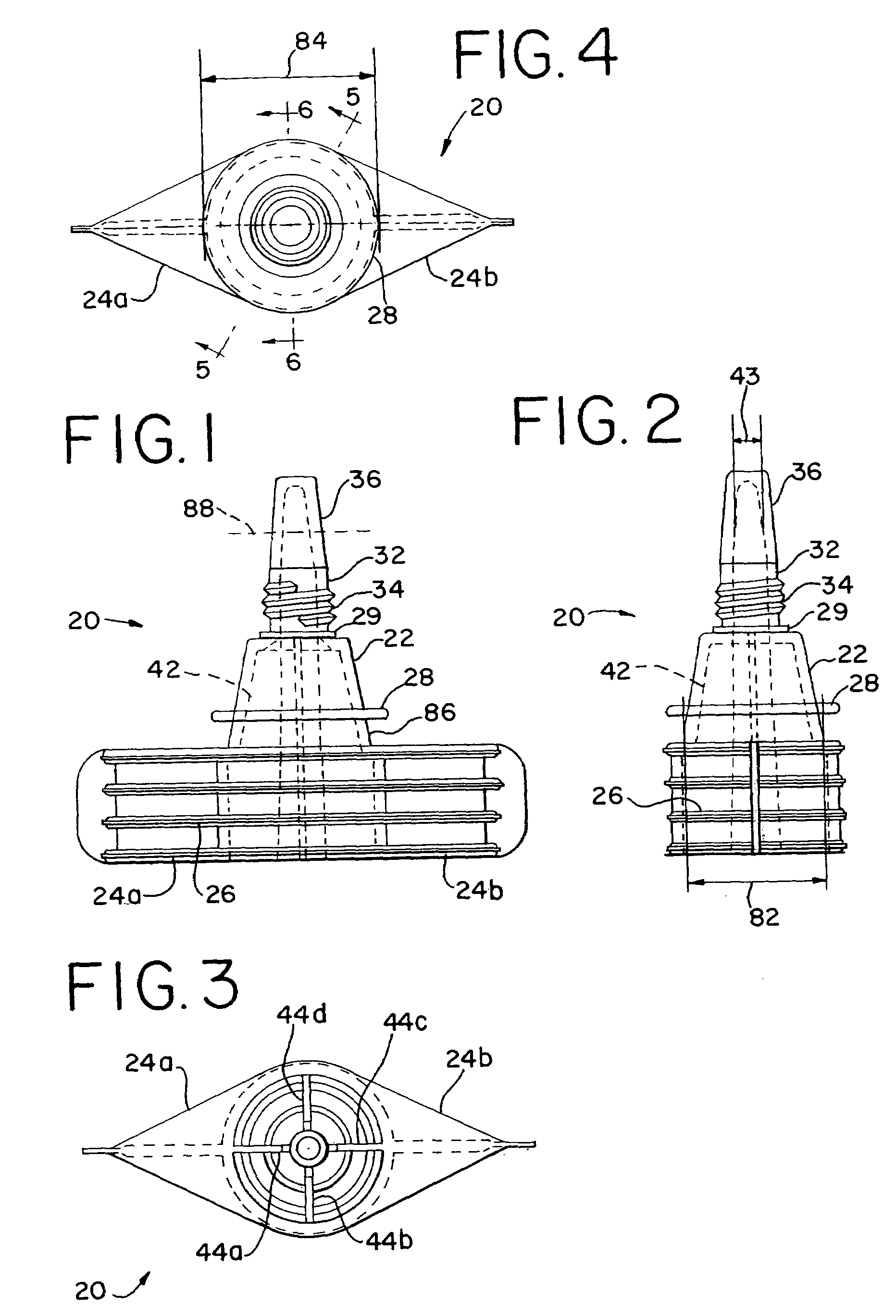
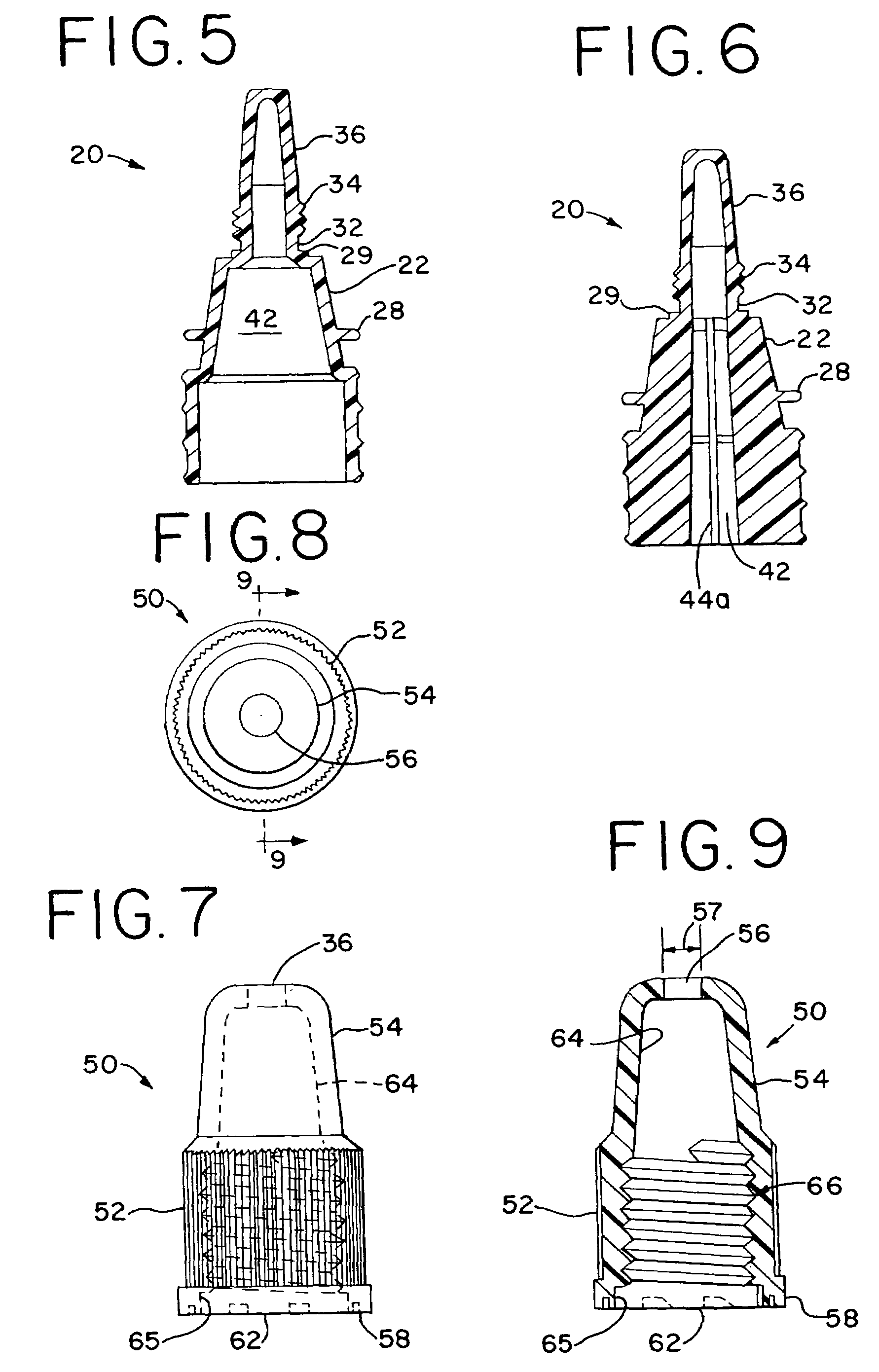
[0025]The dual use decorating device of the present invention includes a fitment disposed within a container or pouch and a nozzle cap secured to the fitment. The fitment portion is illustrated in FIGS. 1–6 while the nozzle cap is illustrated in FIGS. 7–9.

[0026]As shown in FIGS. 1–4, a fitment of the dual use decorating device according to the present invention is indicated in general at 20. In this embodiment, the fitment 20 features a main body 22 having a pair of ears 24a and 24b extending outwardly from the main body 22. Ear 24a extends outwardly from one side of the main body 22 while ear 24b extends outwardly from the opposite side of the main body. As shown in FIGS. 3 and 4, the ears 24a, 24b have a triangular shape. The ears may also be formed from other shapes, such as rectangular or circular. Each ear 24a, 24b preferably includes multiple ridges 26 that extend along the outer surface of each ear. As will be later described, ears 24a and 24b are used to join the fitment 20 ...


PUM

PropertyMeasurementUnit
diameteraaaaaaaaaa
diameteraaaaaaaaaa
viscousaaaaaaaaaa

Abstract

A container has an opening and a nozzle disposed within the opening. The nozzle has a sealed tip that extends from the opening. A cap having an opening therethrough is secured to the nozzle. To use the container, the tip of the nozzle is cut to enable a viscous fluid to dispense therefrom at a first thickness. When the cap is re-secured to the nozzle, the opening of the cap enables the viscous food substance to dispense therefrom at a second thickness that is less than the first thickness.

Description

CROSS REFERENCE TO RELATED APPLICATIONS[0001]This application claims priority to U.S. Provisional Patent Application Ser. No. 60 / 432,802 filed on Dec. 12, 2002.FIELD OF THE INVENTION[0002]The present invention relates generally to hand held dispensers for viscous foodstuffs and, more particularly, to dispensers which may be used to dispense icing on deserts such as cookies, cakes and the like and tips, nozzles and caps for such dispensers.BACKGROUND OF THE INVENTION[0003]Methods of dispensing icing onto cakes, cookies or the like are well known. Traditionally, icing is placed into collapsible paper cones that may be squeezed to dispense the icing through the tip or nozzle at one end of the cone. An example of a collapsible cone is illustrated in U.S. Pat. No. 2,320,496 issued to Wechsler. The collapsible cones, however, may rupture or tear so as to leave the device inoperable.[0004]As an alternative to the paper cones, icing may be dispensed using collapsible or squeezable bulb-shap...

Claims


Application Information

Patent Timeline
Patent Type & Authority Patents(United States)
IPC IPC(8): B65D47/10A21C15/00A23G3/22A23G3/28B65D37/00B65D75/00B65D75/58
CPCA21C15/005A23G3/22A23G3/28B65D75/008B65D75/5883B65D37/00B65D2575/583B29L2031/712B29C65/08B29C66/30223B29C66/53263
Inventor FRANCZYK, CATHERINE
Owner WILTON INDS
Why Eureka
Try Eureka