Gas check valve and application thereof to air chamber packaging structure
A technology of check valve and inflatable packaging, which is applied in pressurized/vaporized packaging, valve devices, control valves, etc., which can solve the difficulty of automatic production of check valves and bags, and limit the degree of automation of inflatable products. Product inflation efficiency, complex check valve processing and other issues, to achieve the effect of improving utilization rate and flexibility, maximizing raw material utilization rate, and improving application value
- Summary
- Abstract
- Description
- Claims
- Application Information
AI Technical Summary
Problems solved by technology
Method used
Image
Examples
Embodiment 1
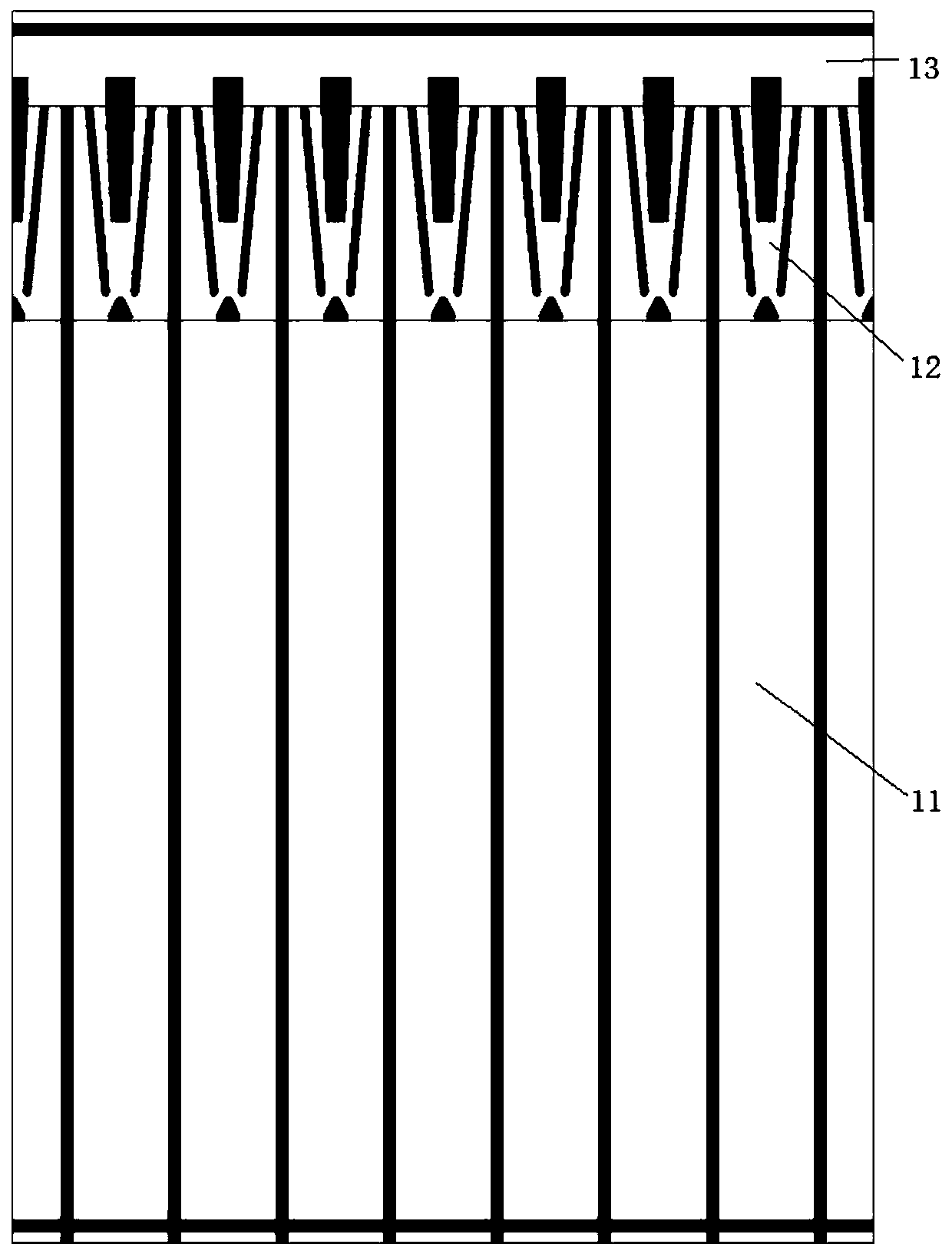
[0045] The setting of the new air valve can make the distribution of the air passage and the direction of the air passage in the same structure without any restrictions. The position of the air valve can also be set separately according to the characteristics of the air column. The inflatable structure under the new inflatable check valve The tile map of the body is as follows Figure 10a As shown, the schematic diagram of three-dimensional molding is shown in Figure 10b shown.
Embodiment 2
[0047] In actual packaging applications, the packaging of a product often requires a combination of different sizes / structures of inflatable cushioning materials. In traditional production methods, only a single size / structure of cushioning materials can be produced in one batch. At the same time, the limitation of raw material specifications leads to the production of small-sized products, which will lead to more waste of layout. Such as Figure 11 As shown, in the production of inflatable materials in the application of the new air valve, the production of materials of different sizes and the imposition between different structures can be realized at the same time, so that the production rate of raw materials is improved, and the processing is convenient and efficient.
Embodiment 3
[0049] The distribution of the new gas check valve in the gas chamber structure and the change of the gas chamber structure
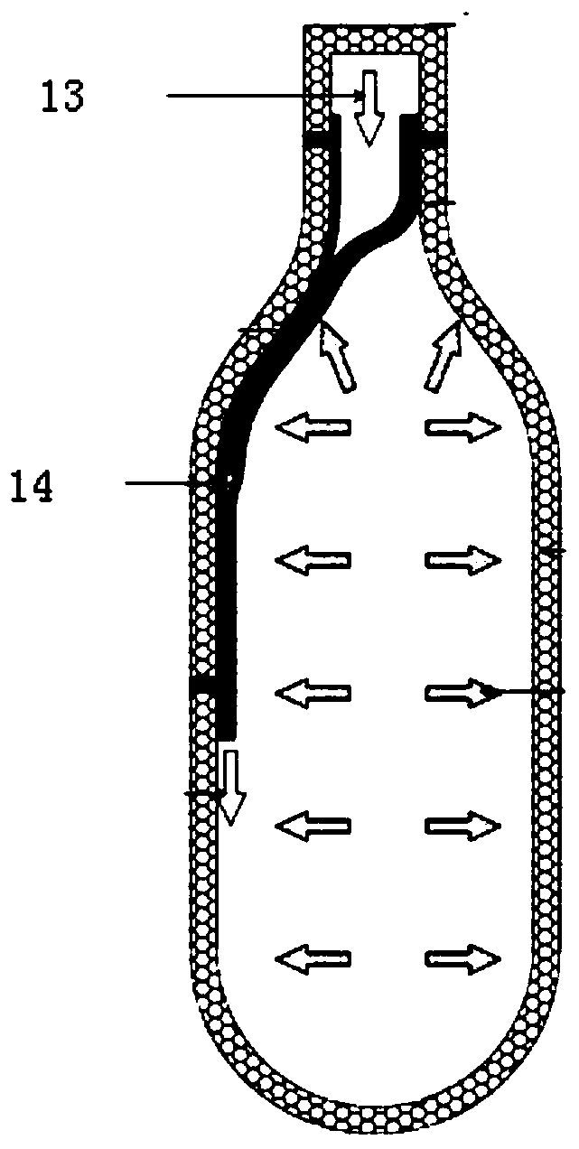
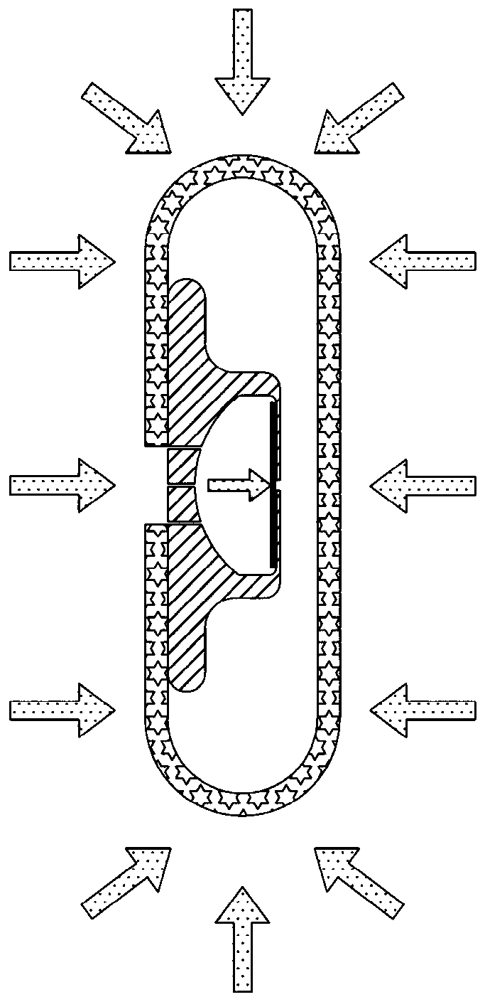
[0050] The new gas check valve is small in size and symmetrical in structure along the center, and can be distributed at any position where an inflatable unit can be formed to form an inflatable buffer according to application requirements. The distribution of the new gas check valve on the air chamber buffer structure can determine the structural shape and density of the gas chamber buffer structure, thereby determining the load capacity and buffer function of the air chamber buffer structure. Such as Figure 12 In the shown air chamber structure, the air chamber unit with a check valve is combined with the non-inflatable airtight unit, and the distribution position and size density of the air chamber unit in the buffer body are more flexible.
PUM
 Abstract
Description
Claims
Application Information
 - R&D
- Intellectual Property
- Life Sciences
- Materials
- Tech Scout
- Unparalleled Data Quality
- Higher Quality Content
- 60% Fewer Hallucinations
Browse by: Latest US Patents, China's latest patents, Technical Efficacy Thesaurus, Application Domain, Technology Topic, Popular Technical Reports.
© 2025 PatSnap. All rights reserved.Legal|Privacy policy|Modern Slavery Act Transparency Statement|Sitemap|About US| Contact US: help@patsnap.com


