
An apparatus for dislodging and removing contaminants from a surface of a machine tool

a technology for cleaning apparatuses and machine tools, which is applied in the direction of boring/drilling machines, turning machine accessories, tableware washing/rinsing machines, etc. it can solve the problems of increasing machine downtime and associated costs, dust collection apparatuses that do not remove contaminants from the surface of machine tool housings, and do not incorporate a spindle-mounted vacuum source, so as to reduce mess and operator involvement, improve space-efficiency, and efficiently clean

Inactive Publication Date: 2006-05-11
FORD MOTOR CO
View PDF10 Cites 10 Cited by
  • Summary
  • Abstract
  • Description
  • Claims
  • Application Information

AI Technical Summary

Benefits of technology

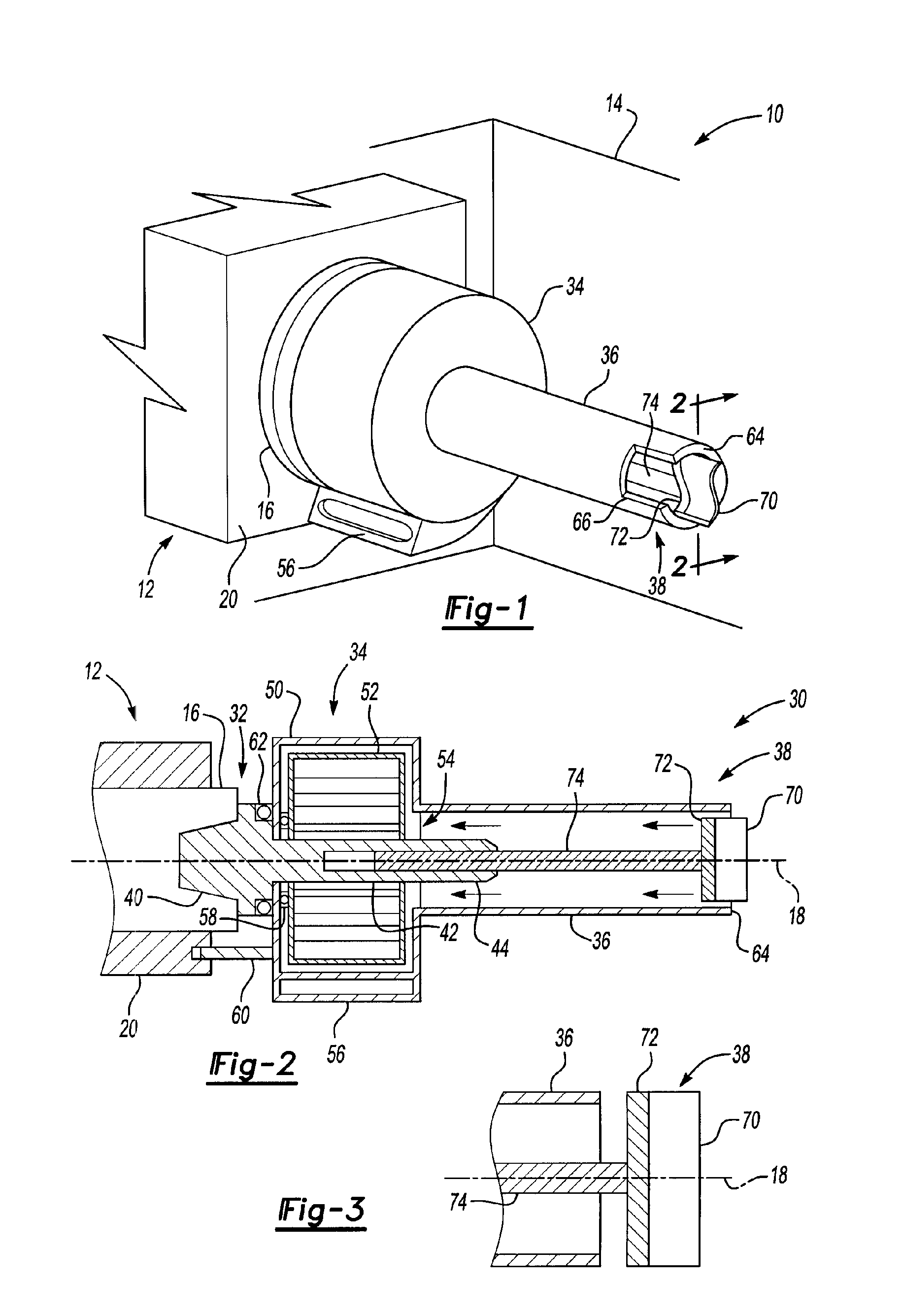
[0008] According to one aspect of the present invention, an apparatus for dislodging and removing contaminants from a surface of a machine tool is provided. The machine tool includes a spindle adapted to turn about an axis of rotation and a housing disposed around and spaced apart from the spindle. The apparatus includes an arbor, a vacuum source, a tube, and a cleaning member. The arbor is adapted to attach to the spindle. The vacuum source is disposed proximate the arbor. The tube is disposed proximate the vacuum source and has a distal end. The cleaning member is disposed proximate the distal end. The cleaning member contacts a surface of the housing to dislodge contaminants. The contaminants are drawn through the tube by the vacuum source. This apparatus permits various machine tool, workpiece, or fixture surfaces to be efficiently cleaned with reduced mess and operator involvement and improves space-efficiency.
[0011] The tube may include a slot disposed proximate the distal end for receiving contaminants. The slot allows the apparatus to capture or scoop up accumulated contaminants and improves the flexibility and utility of the apparatus.
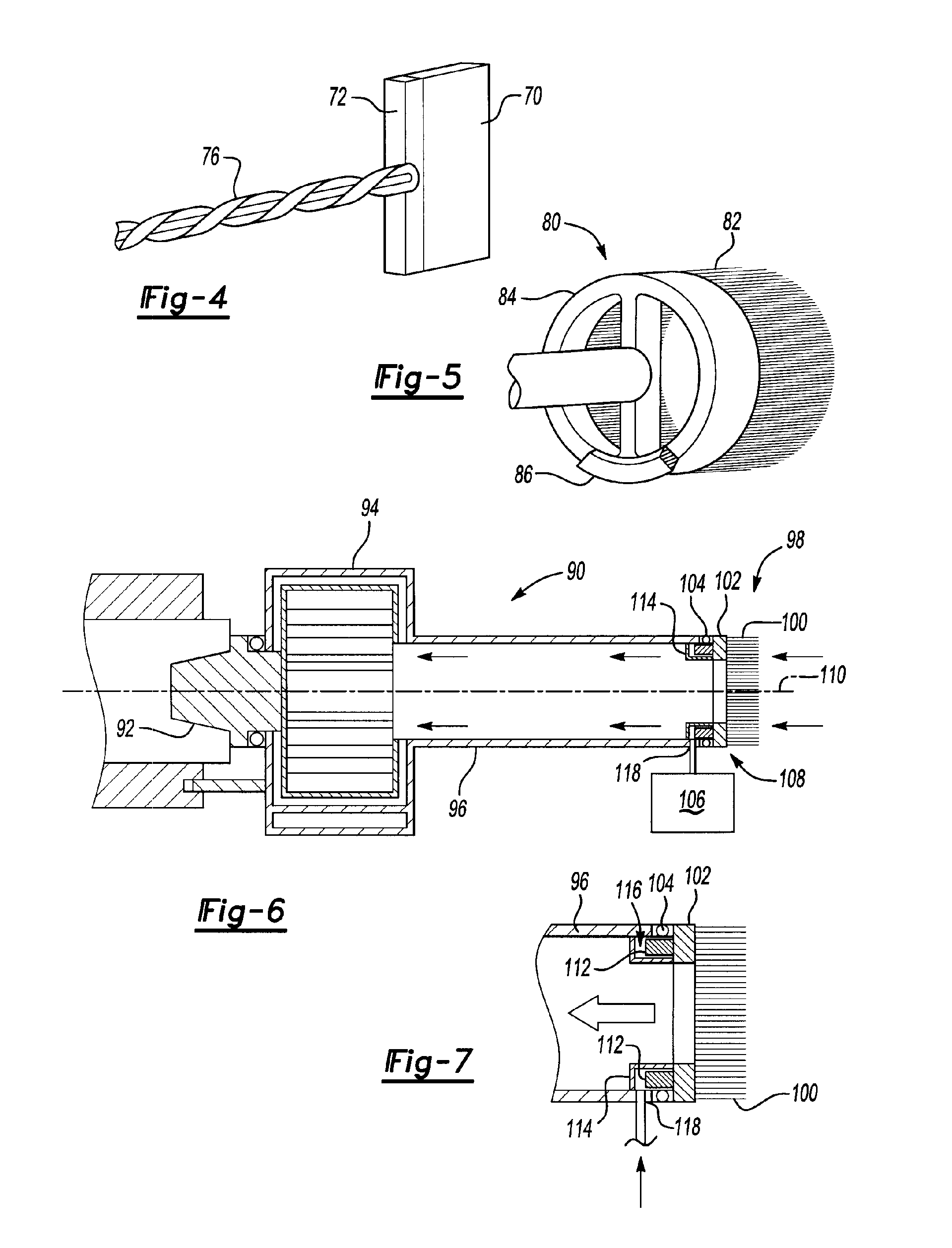
[0015] The rotating cleaning mechanism may include a bearing, a mounting plate, and a power source. The bearing may be disposed proximate the distal end. The mounting plate may be disposed proximate the bearing and may be configured to receive the cleaning member. The power source may be adapted to rotate the mounting plate and cleaning member about the axis of rotation. The rotating cleaning mechanism may also include a tubular housing, an inlet, and a set of vanes extending from the mounting plate and disposed within the tubular housing. Such a configuration provides the flexibility to rotate the cleaning member independent of the spindle.

Problems solved by technology

These manual operations were messy, time consuming, labor intensive, and resulted in increased machine downtime and associated costs.
However, such dust collecting apparatuses did not remove contaminants from machine tool housing surfaces, did not incorporate a rotatable cleaning member, and did not incorporate a spindle-mounted vacuum source.

Method used


Image

  • An apparatus for dislodging and removing contaminants from a surface of a machine tool
  • An apparatus for dislodging and removing contaminants from a surface of a machine tool
  • An apparatus for dislodging and removing contaminants from a surface of a machine tool

Examples


Embodiment Construction

)

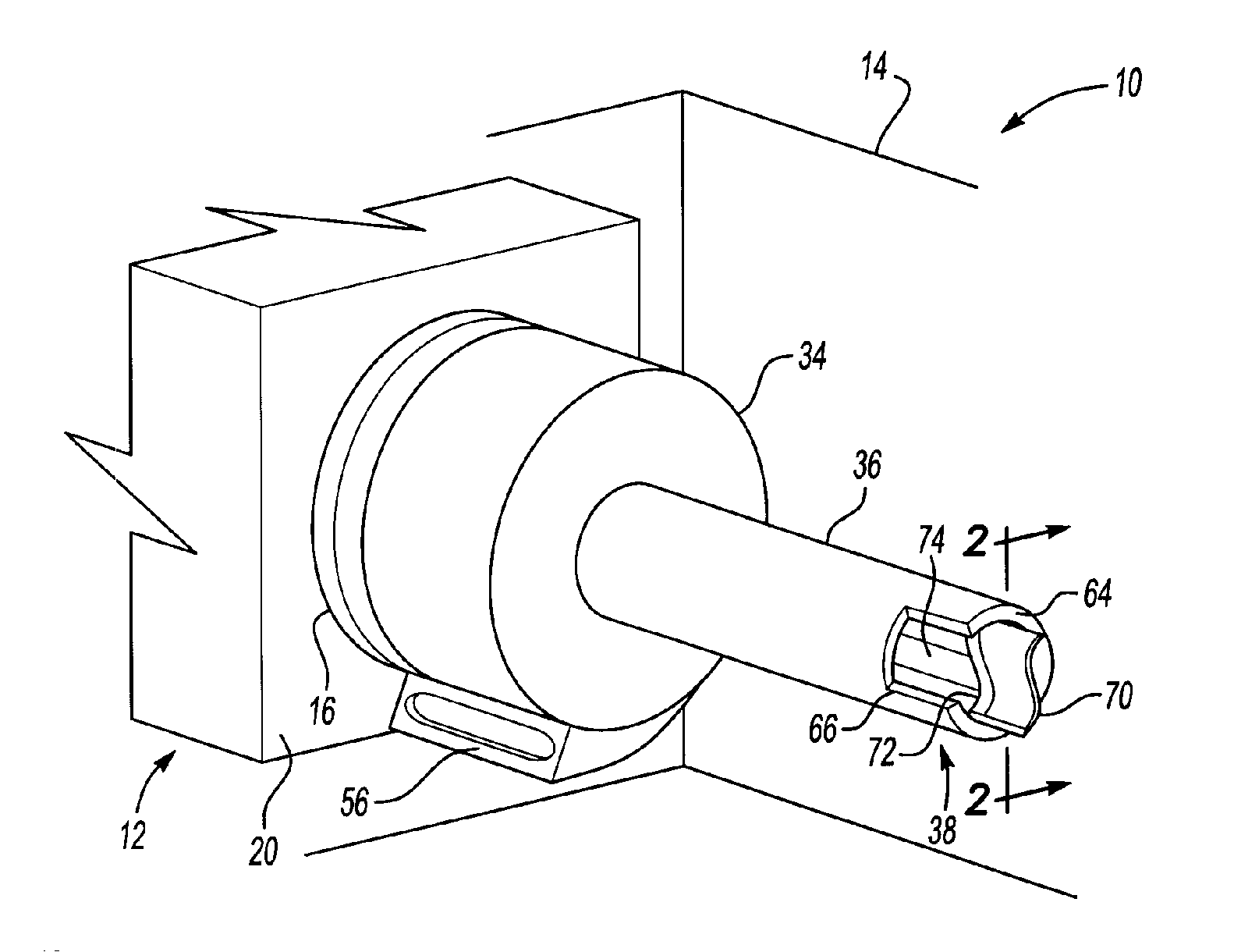
[0026] Referring to FIG. 1, a machine tool 10 is shown. The machine tool 10 may be of any suitable type, such as a computer numerical control (CNC) machine tool, press, or assembly device. In addition, the machine tool 10 may be configured to perform any suitable shaping or finishing operation, such as cutting, shaving, turning, boring, drilling, grinding, reaming, deburring, tapping, forming, milling or polishing.

[0027] In the embodiment shown in FIG. 1, the machine tool 10 includes a spindle assembly 12 and a housing 14. The spindle assembly 12 includes a spindle 16 adapted to rotate about an axis of rotation 18 and a spindle case 20. The spindle 16 may be turned by any suitable device, such as a motor, and at any suitable speed. In addition, the machine tool 10 may be configured to move the spindle assembly 12 along different axes, such as X, Y, and / or Z axes in a manner known by those skilled in the art.

[0028] The housing 14 includes a plurality of panels disposed around and ...


PUM

PropertyMeasurementUnit
Forceaaaaaaaaaa
Poweraaaaaaaaaa

Abstract

An apparatus for dislodging and removing contaminants from a surface of a machine tool. The apparatus includes an arbor, a vacuum source, a tube, and a cleaning member disposed proximate a distal end of the tube. The cleaning member contacts a surface of the machine tool to dislodge contaminants. The contaminants are drawn through the tube by the vacuum source.

Description

BACKGROUND OF THE INVENTION [0001] 1. Field of the Invention [0002] The present invention relates to an apparatus for removing contaminants from a surface of a machine tool, and more particularly to a cleaning apparatus that is selectively coupled to and movable by a machine tool to dislodge and vacuum contaminants. [0003] 2. Background Art [0004] Machine tools can perform a variety of operations to shape and finish a part. Contaminants such as chips, dust, and lubricants are dispersed onto surfaces of the machine tool when such operations are performed. These contaminants must be periodically removed to maintain the stability and quality of the machining process. [0005] Previously, operators cleaned machine tools by spraying pressurized air or coolant against contaminated surfaces to dislodge particulates. These manual operations were messy, time consuming, labor intensive, and resulted in increased machine downtime and associated costs. [0006] Previously, apparatuses for providing...

Claims


Application Information

Patent Timeline
IPC IPC(8): B08B3/04
CPCA46B13/008B08B1/04B08B5/04B08B15/04B23Q11/0046Y10T408/458B23Q2230/002Y10T408/453Y10T408/554Y10T29/4567Y10T408/46B23Q2220/008B08B1/32
Inventor STOLL, ALEXANDER
Owner FORD MOTOR CO
Learn More