
Spatial data mining method, spatial data mining apparatus and storage medium

a technology of spatial data and mining apparatus, applied in data processing applications, instruments, maps/plans/charts, etc., can solve the problems of underdeveloped field of spatial data mining, business cannot satisfactorily cope with their operation, and the calculation time is considerably reduced, and the determination of an optimized area is effective.

Inactive Publication Date: 2006-04-04
IBM CORP
View PDF10 Cites 9 Cited by
  • Summary
  • Abstract
  • Description
  • Claims
  • Application Information

AI Technical Summary

Benefits of technology

[0012]It is another object of the present invention to increase the speed of the spatial data mining processing performed to obtain a distance or an orientation.
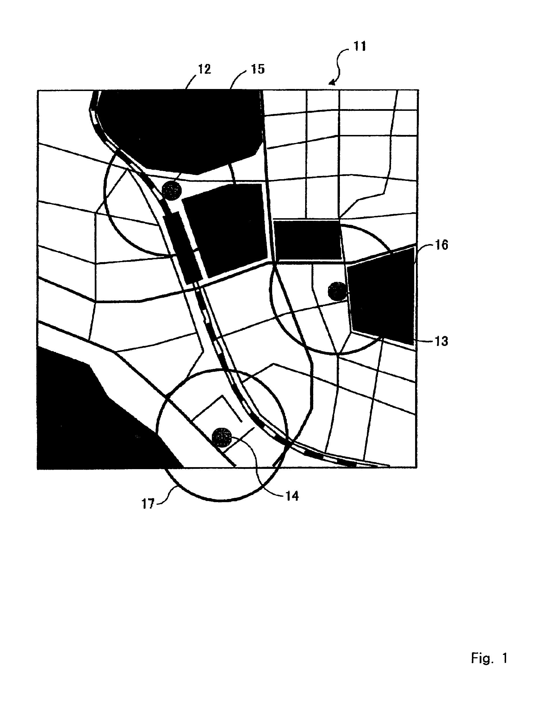
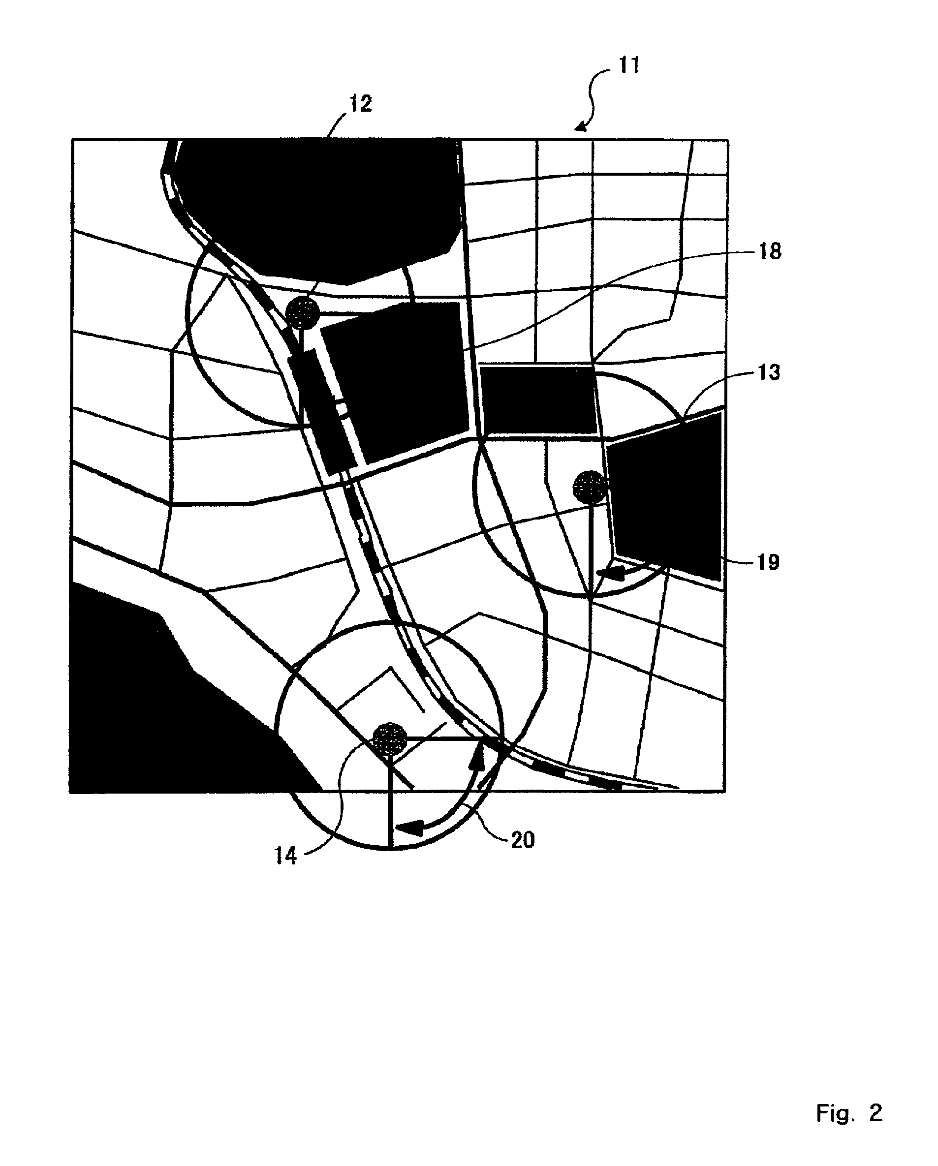
[0027]The display means can use the optimal distance calculated by the optimal distance / orientation calculation means for the display of circular areas, the centers of which are starting points. The display means can also use the optimal orientation, calculated by the optimal distance / orientation calculation means, for the display of fan-shaped portions of the circular areas, the origins of the fan-shaped portions being the starting points at the centers of the circular areas. Thus, for easy understanding, the obtained optimal distance / orientation can be displayed on maps, so that customer usability can be considerably improved.

Problems solved by technology

But since present day spatial data mining requires expensive spatial / geometrical calculations involving a huge amount of data, and since extremely difficult technical problems are frequently encountered, spatial data mining has not been well studied and remains an underdeveloped field.
At this time, a distance such as Y or Z, which is used for optimizing a specific objective function, or a numerical value for strictly determining an angle such as Y1° or Y2°, which is used for optimizing a specific objective function, is requested by many analyzation businesses, and even when the latest conventional techniques are employed, many of those analyzation businesses can not satisfactorily cope with their operation.

Method used


Image

  • Spatial data mining method, spatial data mining apparatus and storage medium
  • Spatial data mining method, spatial data mining apparatus and storage medium
  • Spatial data mining method, spatial data mining apparatus and storage medium

Examples


Embodiment Construction

[0046]A preferred embodiment of the present invention will now be described in detail while referring to the accompanying drawings.

[0047]First, modeling and an algorithm used for the present invention will be described so that the spatial data mining in this embodiment can be easily understood.

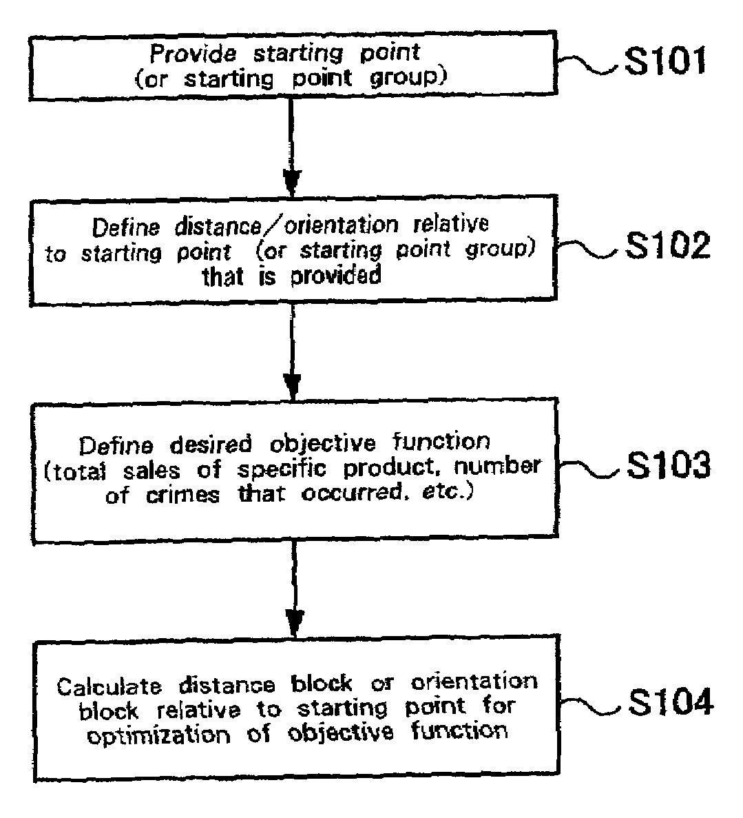
[0048]FIG. 1 is a diagram showing a first modeling example output for this embodiment by a distance optimization engine. On a map 11, distances (or distance blocks), for the optimization of an objective function, measured from starting points (or a starting point group) 12 to 14, which are convenience stores (CS), constitute the predetermined radii of circles 15 to 17. In the example in FIG. 1, the displayed distances, measured from the starting points 12 to 14, used for the optimization of an objective function were obtained by a search run to determine the “distances from convenience stores within which the bag-snatching occurrence rate is maximized.”

[0049]In this example for the embodiment,...


PUM


Abstract

A spatial data mining apparatus for calculating an optimal distance from a database, wherein spatial information, such as addresses, is stored, includes an input mechanism, for the input of an objective function required for the optimization of a distance, an intermediate table generator 30, for employing in the database starting point data and query point data for calculating the distances between each starting point and each query point and for generating an intermediate table, and an optimal distance calculator for calculating a distance based on the intermediate table generated by the intermediate table generator, in order to optimize the value of the objective function that is entered by the input mechanism.

Description

FIELD OF THE INVENTION[0001]The present invention relates to the processing performed for the spatial data mining of databases, and more specifically, relates to a method and an apparatus for the calculation of optimal distances or optimal orientations, which is the basic function of spatial data mining.BACKGROUND OF THE INVENTION[0002]A new processing technique has been introduced whereby spatial information, such as address data, in large databases can be interpreted by applying spatial context and spatial rules. But since present day spatial data mining requires expensive spatial / geometrical calculations involving a huge amount of data, and since extremely difficult technical problems are frequently encountered, spatial data mining has not been well studied and remains an underdeveloped field. However, spatial data mining is considered to be a feasible basic technique that can greatly assist in the development of databases for the information industry or for the GIS (Geographical...

Claims


Application Information

Patent Timeline
IPC IPC(8): G06F7/00G09B29/00G06F17/30G06F19/00G06T7/60
CPCG06F17/30241Y10S707/99943Y10S707/99935Y10S707/921Y10S707/99934Y10S707/99944Y10S707/99933G06F16/29
Inventor MORIMOTO, YASUHIKOKUBO, HARUNOBU
Owner IBM CORP
Learn More