
System and method enabling efficient cache line reuse in a computer system

Active Publication Date: 2006-04-04
SAMSUNG ELECTRONICS CO LTD
View PDF30 Cites 4 Cited by
  • Summary
  • Abstract
  • Description
  • Claims
  • Application Information

AI Technical Summary

Benefits of technology

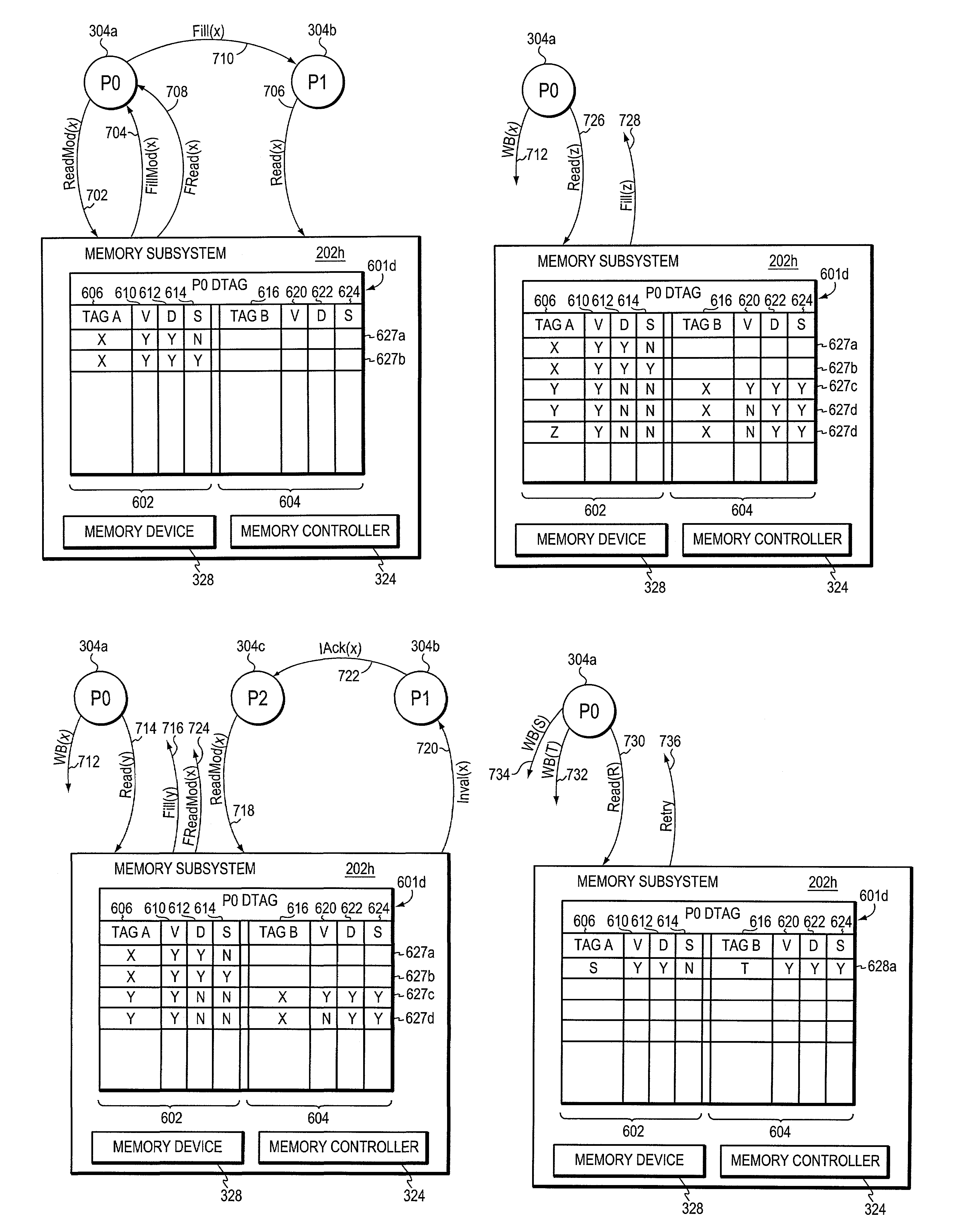
[0022]Pending receipt of the write back of the dirty memory block at main memory, subsequent requests result in searches being made of both the primary and secondary DTAG regions. If a memory reference operation matches an entry in the secondary DTAG region that is both valid and dirty, the memory reference operation is forwarded to the identified processor rather th

Problems solved by technology

Retrieving data from main memory and providing it to a processor can take significant time especially in terms of the high operating speeds of today's processors.
Many caches are static random access memories (SRAMs), which are faster, but more expensive, than dynamic random access memories (DRAMs), which are often used for main memory.
This solution, however, delays the processor's acquisition of the new memory block while it waits for the acknowledgement.
Delays such as these can reduce the computer system's performance.
Associative caches, however, are more expensive and typically smaller than non-associative, mapped caches.
Furthermore, a policy that victimizes non-dirty blocks more often than dirty blocks reduces the effectiveness of the cache.
This solution, however, imposes requirements and complexities on the processor.
Not all processors, moreover, support such pairing of memory reference operations with write-backs.
Ordering constraints, however, increase the complexity of the computer system and, in some cases, may not be feasible.

Method used


Image

  • System and method enabling efficient cache line reuse in a computer system
  • System and method enabling efficient cache line reuse in a computer system
  • System and method enabling efficient cache line reuse in a computer system

Examples


Embodiment Construction

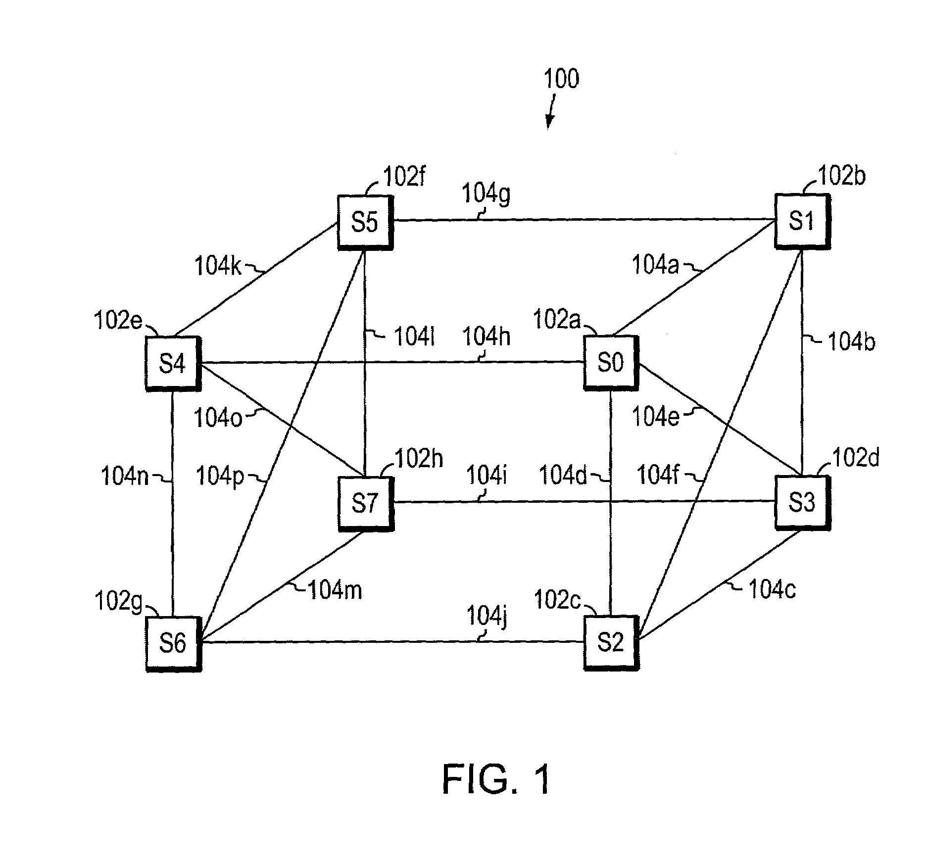
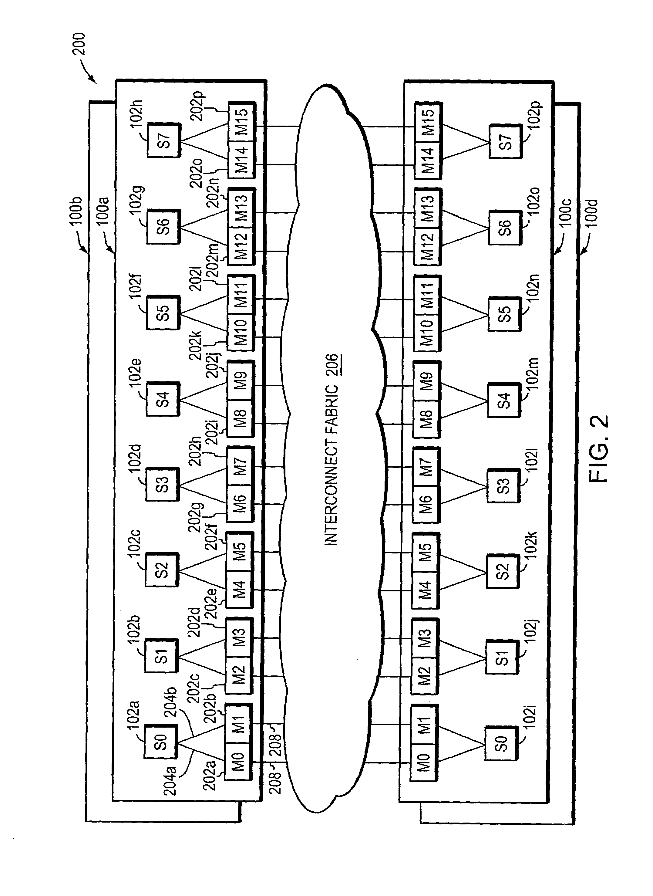
[0031]FIG. 1 is a highly schematic illustration of a preferred multiprocessor node 100 for use with the present invention. The node 100 comprises a plurality of, e.g., eight, sockets, S0–S7, which are designated by reference numerals 102a–h. The eight sockets 102a–h are logically located in three-dimensional space at the corners of a cube, and are interconnected by a plurality of inter-processor links 104a–p. Thus, each socket can communicate with any other socket of the node 100. In the illustrative embodiment, sockets forming two opposing sides of the node 100 are fully interconnected, while the two sides are connected only along the edges of the cube. That is, sockets S0–S3, which form one side of the cube, and S4–S7, which form the opposing side of the cube, are fully interconnected with each other, while the two opposing sides are connected by four inter-socket links 104g–j. As described herein, each socket includes one or more processors and has or is coupled to two main memor...


PUM


Abstract

A system permits unacknowledged write backs in a computer. The computer has a plurality of processors and a shared memory. The shared memory stores data in terms of memory blocks, and each processor has a cache. Associated with each cache line is a tag containing the address of the block at that line, and its state. A duplicate copy of the tag information (DTAG) for each processor cache is also provided, and each section of the DTAG that corresponds to a given processor is organized into a primary DTAG region and a secondary DTAG region. The secondary DTAG region preferably stores tag information for a dirty version of a block, while the write back of the block is in flight to memory. This frees the primary DTAG region to store tag information for a block other than the dirty block, but using the same cache line.

Description

BACKGROUND OF THE INVENTION[0001]1. Field of the Invention[0002]The present invention relates to computer systems and, more specifically, to cache coherent computer systems.[0003]2. Background Information[0004]A computer system typically comprises one or more processors linked to a main memory by a bus or other interconnect. In most computer systems, main memory organizes the instructions and data being stored into units typically referred to as “blocks” each of which is separately addressable and may be of a fixed size. Instructions and data are typically moved about the computer system in terms of one or more blocks.[0005]Ordinarily, a processor will retrieve data, e.g., one or more blocks, from main memory, perform some operation on it, and eventually return the results back to main memory. Retrieving data from main memory and providing it to a processor can take significant time especially in terms of the high operating speeds of today's processors. To reduce such latencies as w...

Claims


Application Information

Patent Timeline
IPC IPC(8): G06F12/00G06F12/08
CPCG06F12/0822G06F12/0804
Inventor TIERNEY, GREGORY E.VAN DOREN, STEPHEN R.
Owner SAMSUNG ELECTRONICS CO LTD
Learn More