Refrigerator

a refrigeration device and compressor technology, applied in refrigeration components, light and heating equipment, veterinary instruments, etc., can solve the problems of insufficient reliability of the compressor b>1/b>, abnormally high discharge temperature, and insufficient discharging temperature, etc., to achieve reliable reduce the discharging temperature of the compressor, and high compression ratio

Inactive Publication Date: 2006-04-11
PANASONIC CORP
View PDF16 Cites 15 Cited by
  • Summary
  • Abstract
  • Description
  • Claims
  • Application Information

AI Technical Summary

Benefits of technology

[0011]The present invention has been accomplished to solve the conventional problem, and it is an object of the invention to provide a refrigerator in which even if carbon dioxide is used as a refrigerant and the refrigerator is operated at high compression ratio, a discharging temperature of the compressor can reliably and safely be reduced.
[0012]To solve the above conventional problem, the refrigerator of the invention comprises an injection pipe for injecting a refrigerant in a supercritical state of a radiator outlet into a cylinder of a compressor. Since the refrigerant in the supercritical state having low enthalpy which is discharged from the radiator is directly injected into the compressor, even if the amount of refrigerant is small, the effect for reducing a discharging temperature of the compressor is great. Further, not a liquid refrigerant but the refrigerant in the supercritical state is injected and thus, liquid compression is not carried out and the reliability is enhanced.
[0013]Further, according to the present invention, even when cooling and warming operations are carried out by switching a four-way valve, since the refrigerant in the supercritical state of an outlet of an outdoor heat exchanger or an outlet of an indoor heat exchanger is injected into the cylinder of the compressor using a check valve, the refrigerant in the supercritical state having the low enthalpy can directly be injected to the compressor, the discharging temperature of the compressor can largely be reduced. Since the refrigerant is in the supercritical state, liquid compression is not carried out and the reliability is enhanced.

Problems solved by technology

According to this conventional refrigerator, when a compression ratio of the compressor 1, i.e., a ratio of a discharging pressure at point D and a drawing pressure at point A shown in FIG. 5 is great at the time of warming operation for example when an outside temperature is low, the discharging temperature becomes abnormally high due to characteristics of the carbon dioxide which is a refrigerant.
For this reason, even if a gas refrigerant separated by the receiver 7 is injected into the compressor 1, the discharging temperature is not lowered sufficiently and the reliability of the compressor 1 is not sufficient.
Thus, a cylinder, a bearing and the like which form the compressing chamber are worn, and reliability thereof can not be secured.

Method used


Image

  • Refrigerator
  • Refrigerator
  • Refrigerator

Examples


embodiment 1

[0020](Embodiment 1)

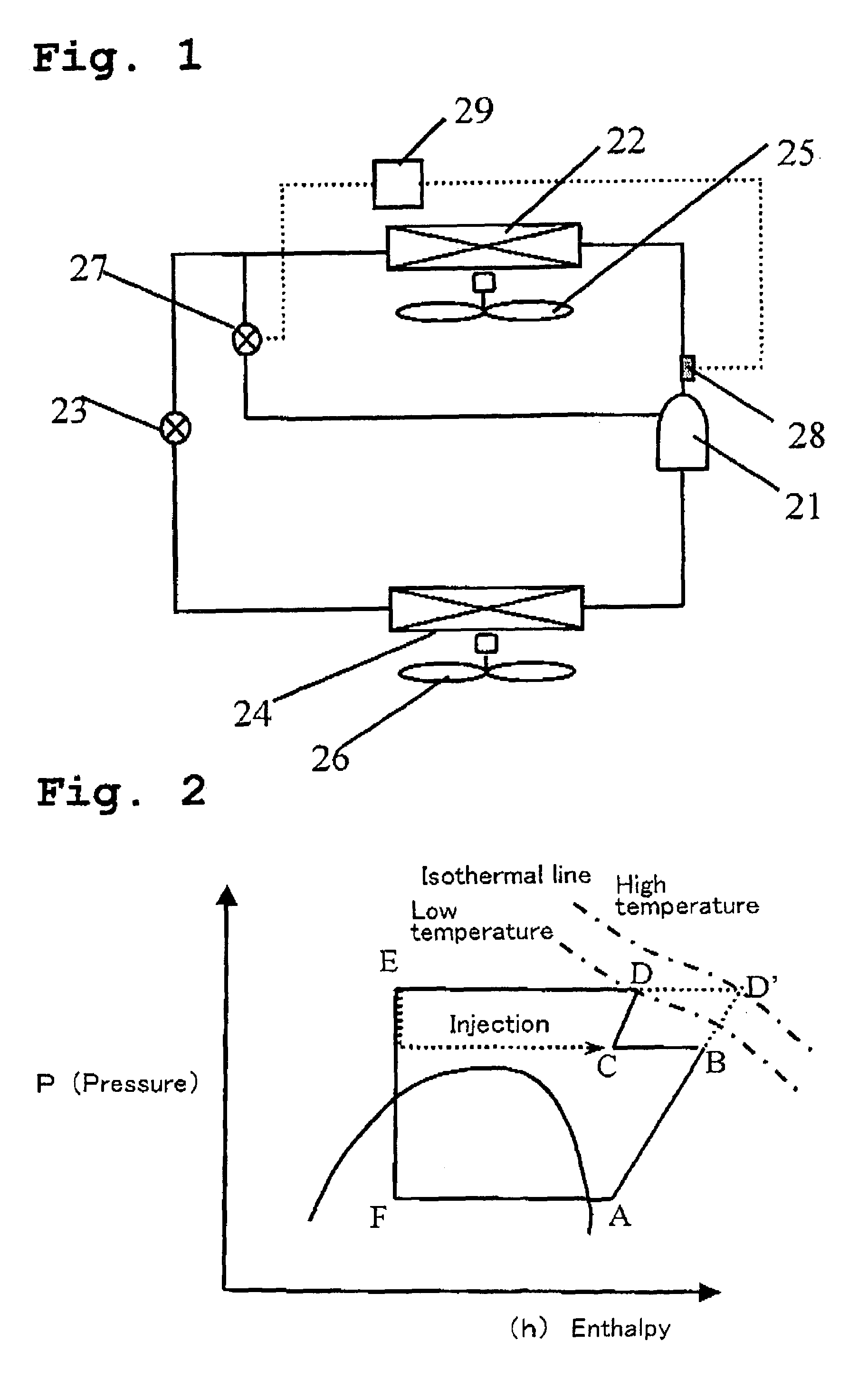
[0021]FIG. 1 is a block diagram of a refrigerator according to an embodiment 1 of the present invention.

[0022]In FIG. 1, a reference number 21 represents a compressor, a reference number 22 represents a radiator, a reference number 23 represents a first throttle apparatus and a reference number 24 represents an evaporator. A reference number 25 represents a fan for the radiator 22 and a reference number 26 represents a fan for the evaporator 24. In this refrigerator, a pipe which is branched off from a pipe on the side of an outlet of the radiator 22 is connected to a cylinder (not shown) of the compressor 21, and a second throttle apparatus 27 is provided in an intermediate portion of the branched pipe, and a refrigerant on the side of the outlet of the radiator 22 is injected into the cylinder of the compressor 21.

[0023]A temperature sensor 28 detects a discharged gas temperature of the compressor 21. A control apparatus 29 compares the discharged gas temperatu...

embodiment 2

[0035](Embodiment 2)

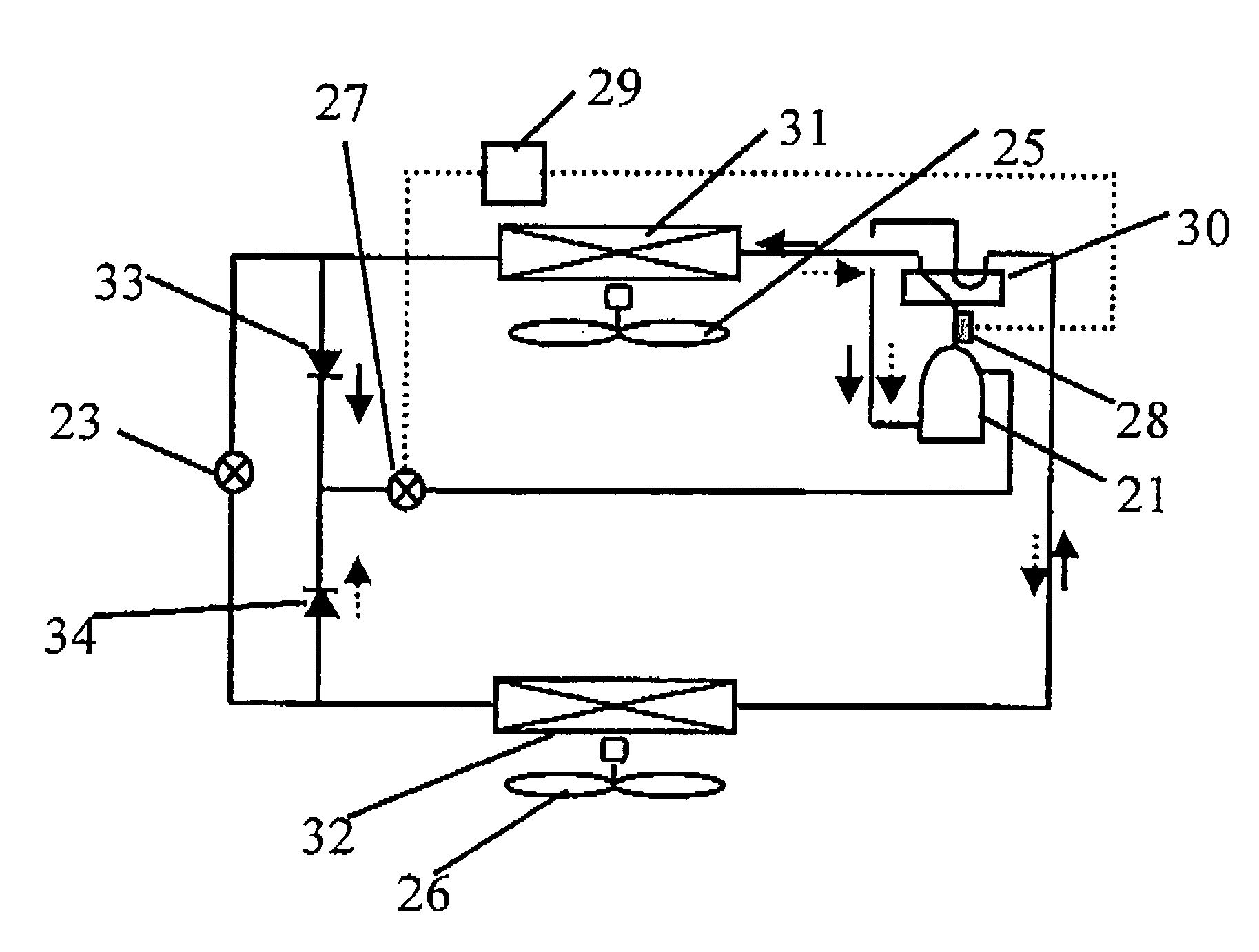
[0036]FIG. 3 is a block diagram of a refrigerator in an embodiment 2 of the present invention.

[0037]In FIG. 3, elements having the same functions as those shown in FIG. 1 are designated with the same symbols and explanation thereof will be omitted.

[0038]The refrigerator in the embodiment 2 includes a four-way valve 30 which switches cooling and warming operations, an outdoor heat exchanger 31, a first throttle apparatus 23 and an indoor heat exchanger 32 are connected to one another to constitute a main circuit of the refrigeration cycle.

[0039]A pipe branched off from a pipe between the outdoor heat exchanger 31 and the first throttle apparatus 23 is connected to a cylinder (not shown) of the compressor 21, and a check valve 33 is connected to an intermediate portion of the branched pipe so that a refrigerant only flows toward the compressor 21 (in a direction shown with solid arrows in FIG. 3). A pipe branched off from a pipe between the indoor heat exchanger 32...


PUM


Abstract

In the case of gas injection, a discharging temperature is not reduced sufficiently, and if an amount of injection is increased, a liquid refrigerant flows into a cylinder and the liquid is compressed, and the reliability can not be ensured.A refrigerator wherein at least a compressor, a radiator, a first throttle apparatus and an evaporator are connected to one another in an annular form to constitute a main circuit of a refrigeration cycle, a refrigerant which can be brought into a supercritical state by the radiator during operation is charged into the refrigeration cycle, the refrigerator comprises an injection pipe for injecting the refrigerant on the side of an outlet of the radiator into a cylinder of the compressor.

Description

TECHNICAL FIELD[0001]The present invention relates a refrigerator used in an air conditioner or the like.BACKGROUND TECHNIQUE[0002]FIG. 4 shows a conventional refrigerator (see Patent Document 1 for example). In FIG. 4, a reference number 1 represents a compressor, a reference number 2 represents an outdoor heat exchanger, a reference number 3 represents an indoor heat exchanger, a reference number 4 represents an accumulator and a reference number 5 represents a four-way valve, The outdoor heat exchanger 2 and the indoor heat exchanger 3 are connected to each other through a refrigerant passage 17. A refrigerant passage 17 is provided with the first expansion valve 11, the second expansion valve 12 and a third, expansion valve 13 in series.[0003]The refrigerant passage 17 between the first expansion valve 11, and the second expansion valve 12 is provided with a receiver 7 for separating gas and liquid from each other. An inner heat exchanger 8 includes a high pressure-side heat tra...

Claims


Application Information

Patent Timeline
Patent Type & Authority Patents(United States)
IPC IPC(8): F25B13/00F25B1/00F25B1/10F25B9/00F25B31/00
CPCF25B1/10F25B9/008F25B13/00F25B31/006F25B2309/061F25B2700/1933F25B2400/23F25B2600/2509F25B2700/21152F25B2700/1931F25B2400/13A61D7/00
Inventor NAKATANI, KAZUOKAWABE, YOSHIKAZUINOUE, YUJIOKAZA, NORIHO
Owner PANASONIC CORP
Why Eureka
Try Eureka