Supercharge Your Innovation With Domain-Expert AI Agents!

High-pressure fuel pump

a fuel pump and high-pressure technology, which is applied in the direction of fuel injecting pumps, machines/engines, positive displacement liquid engines, etc., can solve the problems of inoperable high-pressure fuel pumps, difficult to form the outer peripheral surface of the tappet into a complicated configuration, and the piston cannot pressurize fuel. to achieve the effect of improving the durability of the tapp

Inactive Publication Date: 2006-04-11
MITSUBISHI ELECTRIC CORP
View PDF13 Cites 10 Cited by
  • Summary
  • Abstract
  • Description
  • Claims
  • Application Information

AI Technical Summary

Benefits of technology

[0008]The present invention is intended to obviate the problems as referred to above, and has for its object to provide a high-pressure fuel pump which is of a simple construction and which is capable of distributing the position of abutment or contact between a tappet and a cam so as to improve durability of the tappet without causing seizure of a piston.

Problems solved by technology

In this case, there take place local wear of the tappet and resultant wear of the cam surface accompanying the tappet wear in accordance with a long period of use thereof, and if a prescribed amount of lift of the tappet provided by the cam profile is impaired, there might arise a situation where it becomes impossible for the piston to pressurize fuel to a desired pressure, thus leading to an inoperative condition of the high-pressure fuel pump.
However, the high-pressure fuel pumps as constructed above have the following problems.
That is, in the method described in the above-mentioned first patent document, it is difficult to form the outer peripheral surface of the tappet into a complicated configuration.
In addition, in the method described in the above-mentioned second patent document, a force acting on the piston in a diametral or radial direction thereof is generated due to eccentricity between the cam and the piston, thereby causing seizure of the piston.

Method used


Image

  • High-pressure fuel pump
  • High-pressure fuel pump
  • High-pressure fuel pump

Examples


embodiment 1

[0023]FIG. 1 shows a hydraulic circuit diagram including a high-pressure fuel supply system 1.

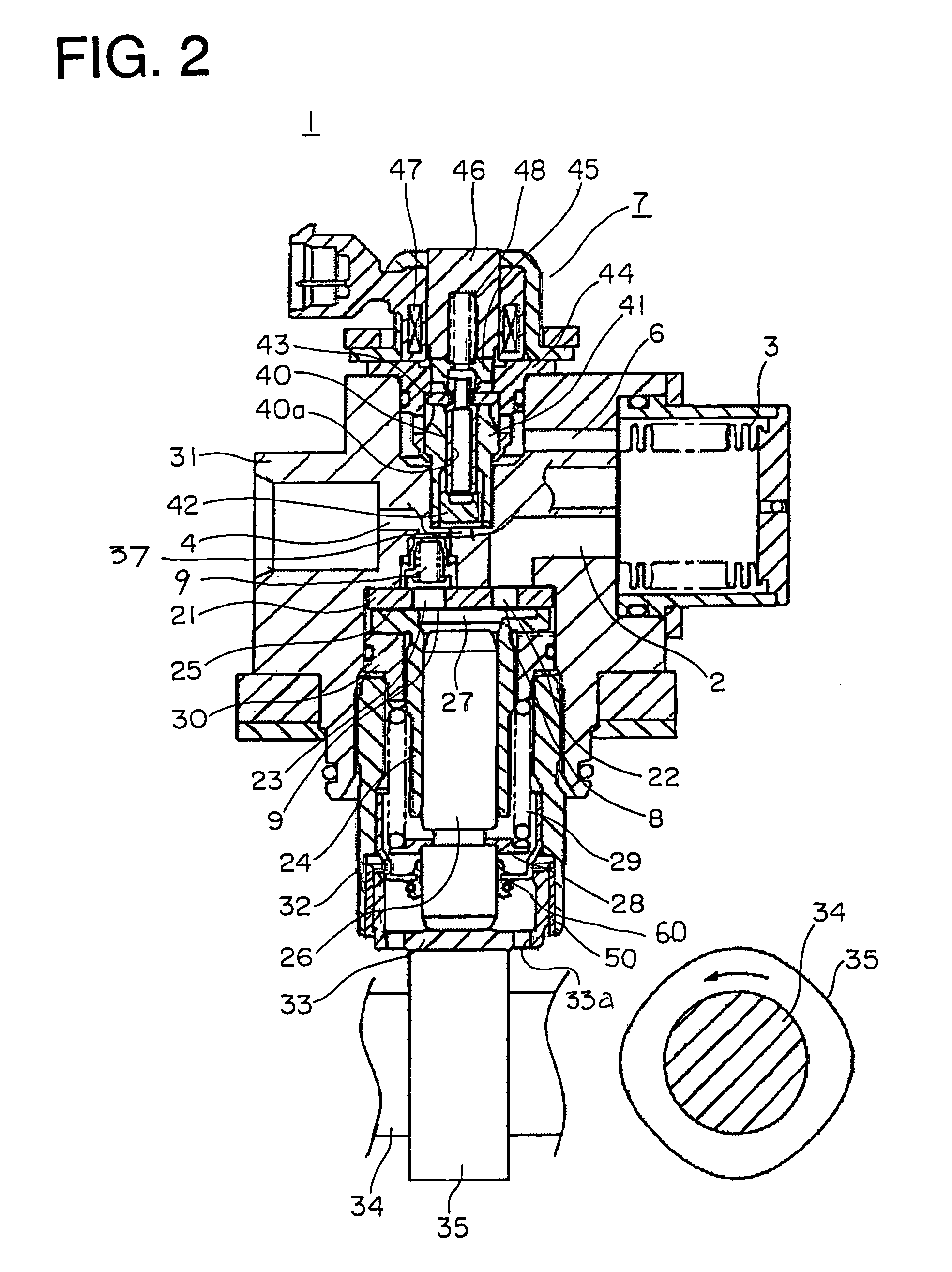
[0024]The high-pressure fuel supply system 1 includes: a low-pressure damper 3 arranged on a low-pressure fuel suction passage 2 for absorbing the pulsation of a low-pressure fuel; a high-pressure fuel pump 5 for pressurizing the low-pressure fuel from the low-pressure damper 3 to discharge it to a high-pressure fuel discharge passage 4; a relief passage 6 connecting between a suction side of the high-pressure fuel pump 5 and a pressurization chamber; and an electromagnetic valve 7 arranged on the relief passage 6 and being operated to open for adjusting the amount of fuel discharged from the high-pressure fuel pump 5. The high-pressure fuel pump 5 has a suction valve 8 and a discharge valve 9.

[0025]In the neighborhood of the high-pressure fuel supply system 1, there are provided a fuel tank 10, a low-pressure fuel pump 11 arranged in the fuel tank 10, a low-pressure regulator 12 branched f...

embodiment 2

[0043]FIG. 6 is a cross sectional view of a high-pressure fuel pump according to a second embodiment of the present invention. FIG. 7 is an enlarged view of essential portions of the high-pressure fuel pump shown in FIG. 6. FIG. 8 is a cross sectional view taken along line VIII—VIII of FIG. 6.

[0044]This second embodiment is different from the above-mentioned first embodiment in the followings. That is, a sleeve 51 is of a flexibly deformable C-shaped configuration; an axially wide groove 53a is formed on the outer peripheral surface of a tappet 53; and a ring 54 is arranged between an end of a housing 32 and the tappet 53 for preventing the sleeve 51 and the tappet 53 from dropping out from the housing 32.

[0045]After the sleeve 51 is inserted onto the tappet 53 in the axial direction thereof, it is engaged into the groove 53a formed on the outer peripheral surface of the tappet 53 by slightly deforming the sleeve 51 in a direction to decrease its radius of curvature at the location ...

embodiment 3

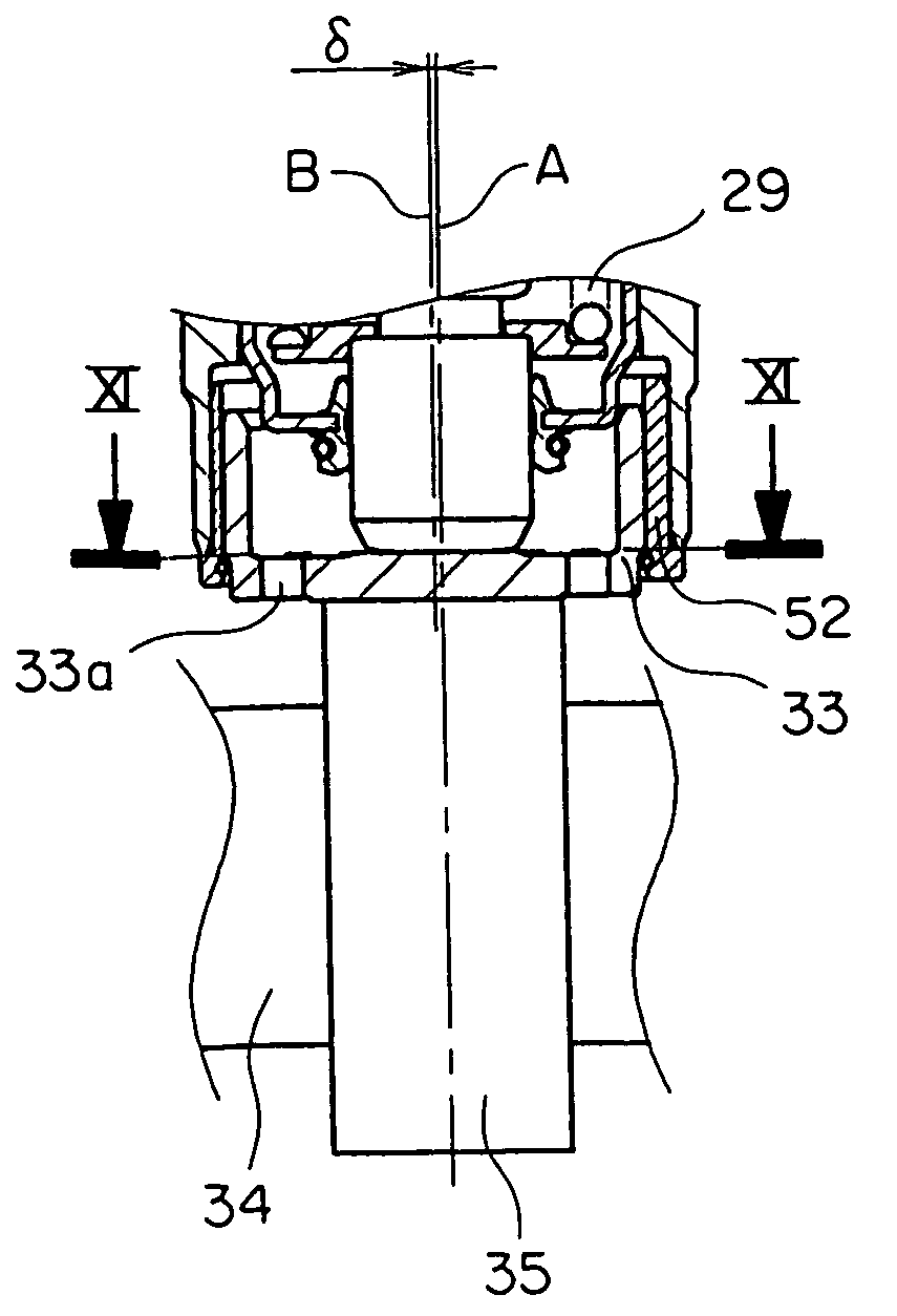
[0047]FIG. 9 is a cross sectional view of a high-pressure fuel pump according to a third embodiment of the present invention. FIG. 10 is an enlarged view of essential portions of the high-pressure fuel pump as shown in FIG. 9. FIG. 11 is a cross sectional view taken along line XI—XI of FIG. 9.

[0048]In this third embodiment, the central point of contact of a cam 35, which is in contact with a tappet 33, is on the central axis A of a piston 26, and the central axis B of the tappet 33 is apart a distance δfrom the central axis A of the piston 26. A sleeve 52 is constructed in a such a manner that the thickness of the sleeve 52 varies gradually along a circumferential direction thereof, as a result of which the central point of the outer diameter of the sleeve 52 does not coincide with the central point of the inner diameter thereof.

[0049]According to this third embodiment, the central point of contact of the cam 35 is arranged apart the distance 6 from the central axis B of the tappet ...


PUM


Abstract

A high-pressure fuel pump of a simple construction is capable of distributing the position of contact between a tappet and a cam so as to improve durability of the tappet without causing seizure of a piston. A cylinder is arranged in a housing, and the piston is received in the cylinder for sliding reciprocation so that fuel is sucked into the cylinder and pressurized by the piston. The tappet is arranged inside one end of the housing for reciprocation, and contacts the cam, which rotates with a camshaft of an engine, so as transmit a driving force of the engine to the piston. A sleeve is arranged between the tappet and the housing, and clearance fitted to an outer peripheral surface of the tappet and an inner peripheral surface of the housing. The tappet is caused to rotate on its own axis by a frictional force generated between the cam and the tappet.

Description

BACKGROUND OF THE INVENTION[0001]1. Field of the Invention[0002]The present invention relates to a high-pressure fuel pump for supplying a high-pressure fuel to an internal combustion engine.[0003]2. Description of the Related Art[0004]In a known high-pressure fuel pump, a tappet enclosed by a housing repeats vertical movements in alignment with a piston in accordance with the abutment or contact of the tappet with a cam while acting against the sliding resistance of an inner wall surface of the housing. The tappet does not basically rotate on its own axis, and hence the abutment of the tappet with the cam is always performed at the same locations or portions. As a result, wearing of the tappet progresses concentratedly only at those portions thereof at which the tappet is in line contact with the cam. In this case, there take place local wear of the tappet and resultant wear of the cam surface accompanying the tappet wear in accordance with a long period of use thereof, and if a pr...

Claims


Application Information

Patent Timeline
Patent Type & Authority Patents(United States)
IPC IPC(8): F01B9/06F02M59/10F02M59/20F02M59/44F04B1/04
CPCF02M59/102F04B1/0439F02M2200/02
Inventor URYU, TAKUYAONISHI, YOSHIHIKO
Owner MITSUBISHI ELECTRIC CORP
Features
  • R&D
  • Intellectual Property
  • Life Sciences
  • Materials
  • Tech Scout
  • Unparalleled Data Quality
  • Higher Quality Content
  • 60% Fewer Hallucinations
Learn More