
Methods and apparatus to control downhole tools

Inactive Publication Date: 2006-04-11
WEATHERFORD TECH HLDG LLC
View PDF37 Cites 121 Cited by
  • Summary
  • Abstract
  • Description
  • Claims
  • Application Information

AI Technical Summary

Benefits of technology

[0019]The present invention generally provides a downhole tool with an improved means of transmitting data to and from the tool through the use of wired pipe capable of transmitting a signal and/or power between the surface of the well and any components in a tubular st

Problems solved by technology

There are problems associated with the use of MWD tools, primarily related to their capacity for transmitting information.
Additionally, the amount of data transferable in time using a MWD is limited.
Also, mud pulse systems used by an MWD device are ineffective in compressible fluids, like those used in underbalanced drilling.
Wireline control of downhole components provides adequate data transmission of 1,200 bits per second but includes a separate conductor that can obstruct the wellbore and can be damaged by the insertion and removal of tools.
One problem arising with the use of wired pipe is transferring signals between sequential joints of drill string.
Despite the variety of means for transmitting data up and down a string of components, there are some components that are especially challenging for use with wired pipe.
For example, the relative motion between an inner mandrel and an outer housings of jars, slingers, and bumper subs can create a problem in signal transmission, especially when a conductor runs the length of the tool.
This problem can apply to any type of tool that has inner and outer bodies that move relative to one another in an axial direction.
A drilling jar is a tool employed when either drilling or production equipment has become stuck to such a degree that it cannot be readily dislodged from the wellbore.
Methods to run a wire through a jar or tool of this type have not been addressed historically because the technology to send and receive high-speed data down a wellbore did not exist.
There are other tools that could benefit from real time adjustment and control but that have not been automated due to the lack of effective and usable technology for transmitting signals and power downhole.

Method used


Image

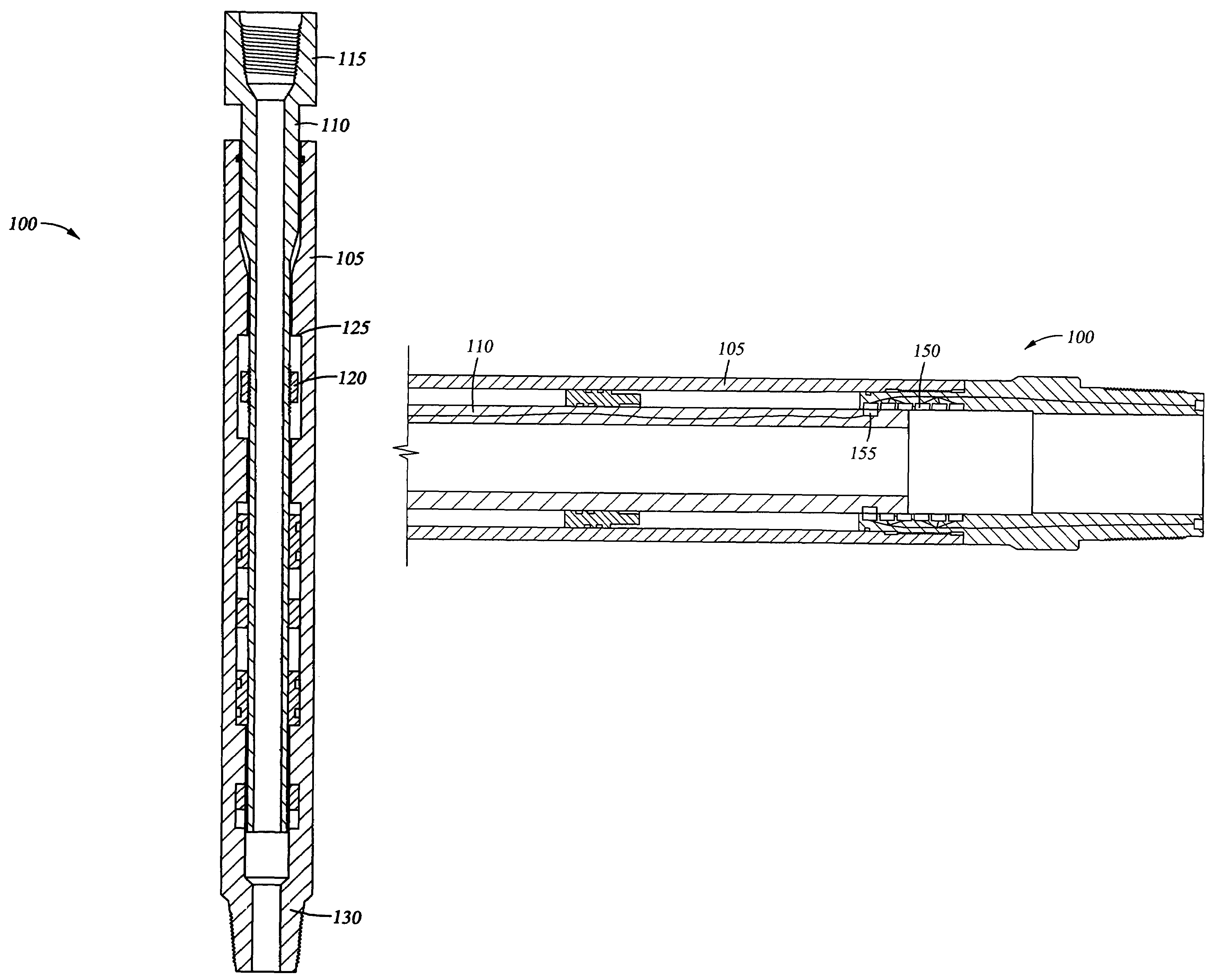
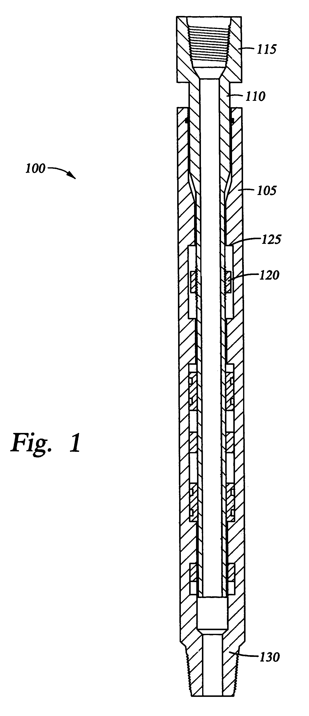
  • Methods and apparatus to control downhole tools
  • Methods and apparatus to control downhole tools
  • Methods and apparatus to control downhole tools

Examples


Embodiment Construction

[0033]The present invention provides apparatus and methods for controlling and powering downhole tools through the use of wired pipe.

[0034]Using high-speed data communication through a drill string and running a wire through a drilling jar, a jar can be controlled from the surface of a well after data from the jar is received and additional data is transmitted back to the jar to affect its performance. Alternately, the jar can have a programmed computer on board or in a nearby member that can manipulate physical aspects of the jar based upon operational data gathered at the jar.

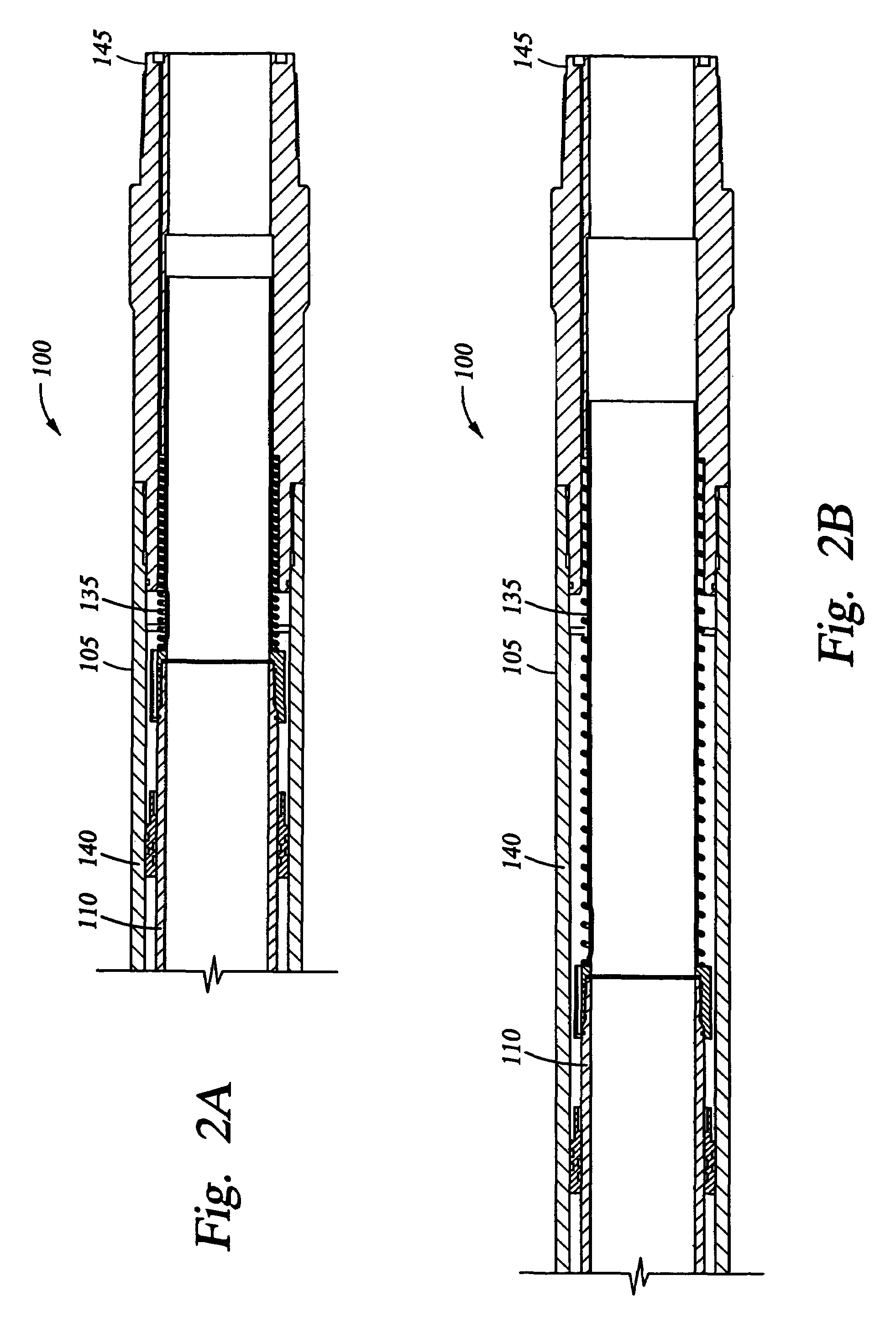
[0035]FIG. 2A illustrates a jar 100 in a retracted position and FIG. 2B shows the jar in an extended position. The jar 100 includes a coiled spring 135 having a data wire disposed in an interior thereof, running from a first 140 to a second end 145 of the tool 100. The coiled spring and data wire is of a length to compensate for relative axial motion as the tool 100 is operated in a wellbore. In the embodimen...


PUM


Abstract

The present invention generally provides a downhole tool with an improved means of transmitting data to and from the tool through the use of wired pipe capable of transmitting a signal and / or power between the surface of the well and any components in a drill string. In one aspect, a downhole tool includes a body, and a mandrel disposed in the body and movable in relation to the body. A conducive wire runs the length of the body and permits signals and / or power to be transmitted though the body as the tool changes its length.

Description

CROSS-REFERENCE TO RELATED APPLICATIONS[0001]This application is a continuation of U.S. patent application Ser. No. 09 / 976,845, filed Oct. 12, 2001, now U.S. Pat. No. 6,655,460, which is incorporated herein by reference.BACKGROUND OF THE INVENTION[0002]1. Field of the Invention[0003]The present invention relates to downhole tools. More particularly, the invention relates to the control of downhole tools in a drill string from the surface of a well.[0004]2. Description of the Related Art[0005]Communication to and from downhole tools and components during drilling permits real time monitoring and controlling of variables associated with the tools. In some instances pulses are sent and received at the surface of a well and travel between the surface and downhole components. In other instances, the pulses are created by a component in a drill string, like measuring-while-drilling (“MWD”) equipment. MWD systems are typically housed in a drill collar at the lower end of the drill string. ...

Claims


Application Information

Patent Timeline
IPC IPC(8): E21B4/12E21B31/107E21B7/06E21B31/113E21B47/12
CPCE21B7/06E21B31/107E21B47/12E21B31/1135E21B31/113
Inventor BAILEY, THOMAS F.NERO, MICHAELWILSON, TIMOTHY L.
Owner WEATHERFORD TECH HLDG LLC
Learn More