Bi-directional thruster pig apparatus and method of utilizing same

a pig apparatus and thruster technology, applied in the direction of drilling pipes, drilling rods, drilling holes/well accessories, etc., can solve the problems of buckling or coiling of the tubing, the weight of the tube no longer acts as a straightening of the coiled tubing, and the inability of art devices to effectively insert more than about 3 pieces, etc., to achieve the effect of eliminating buckling or coiling of the coil tubing

Inactive Publication Date: 2006-04-11
SUPERIOR ENERGY SERVICES LLC
View PDF59 Cites 31 Cited by
  • Summary
  • Abstract
  • Description
  • Claims
  • Application Information

AI Technical Summary

Benefits of technology

[0033]It is a further object of the present invention to provide a thruster pig apparatus attached to the end of coil tubing which through a method of pushing the pig through the pipeline via pressure at the rear of the pig allows the pig to carry the coil tubing along the pipeline for distances greater than ten miles yet eliminate buckling or coiling in the coil tubing during use.

Problems solved by technology

A common problem found in the art of injecting coiled tubing down a pipeline is that the tubing may be bent or kinked, i.e., the tubing becomes helical, down the well due to the large forces pushing against it and the weight of the tubing itself.
In addition, the weight of the tube no longer acts to straighten the coiled tubing, and the coil encourages coiling in the pipe.
As a result of this and other problems, such prior art devices cannot effectively insert more than about 3,000 to about 5,000 feet (900 to 1500 meters) of tubing in substantially horizontal pipe.
However, over large distances over two or more miles, such a device is still not suitable.
This device, although effective, cannot be operated to allow the device to continue to simultaneously move forward in the pipeline while obstructions in the pipeline are being cleaned away.
Also, there is no provision in this device to allow pieces of debris to flow up to the surface behind the pig, as the pig moves forward to destroy the obstructions in the pipeline.

Method used


Image

  • Bi-directional thruster pig apparatus and method of utilizing same
  • Bi-directional thruster pig apparatus and method of utilizing same
  • Bi-directional thruster pig apparatus and method of utilizing same

Examples


Embodiment Construction

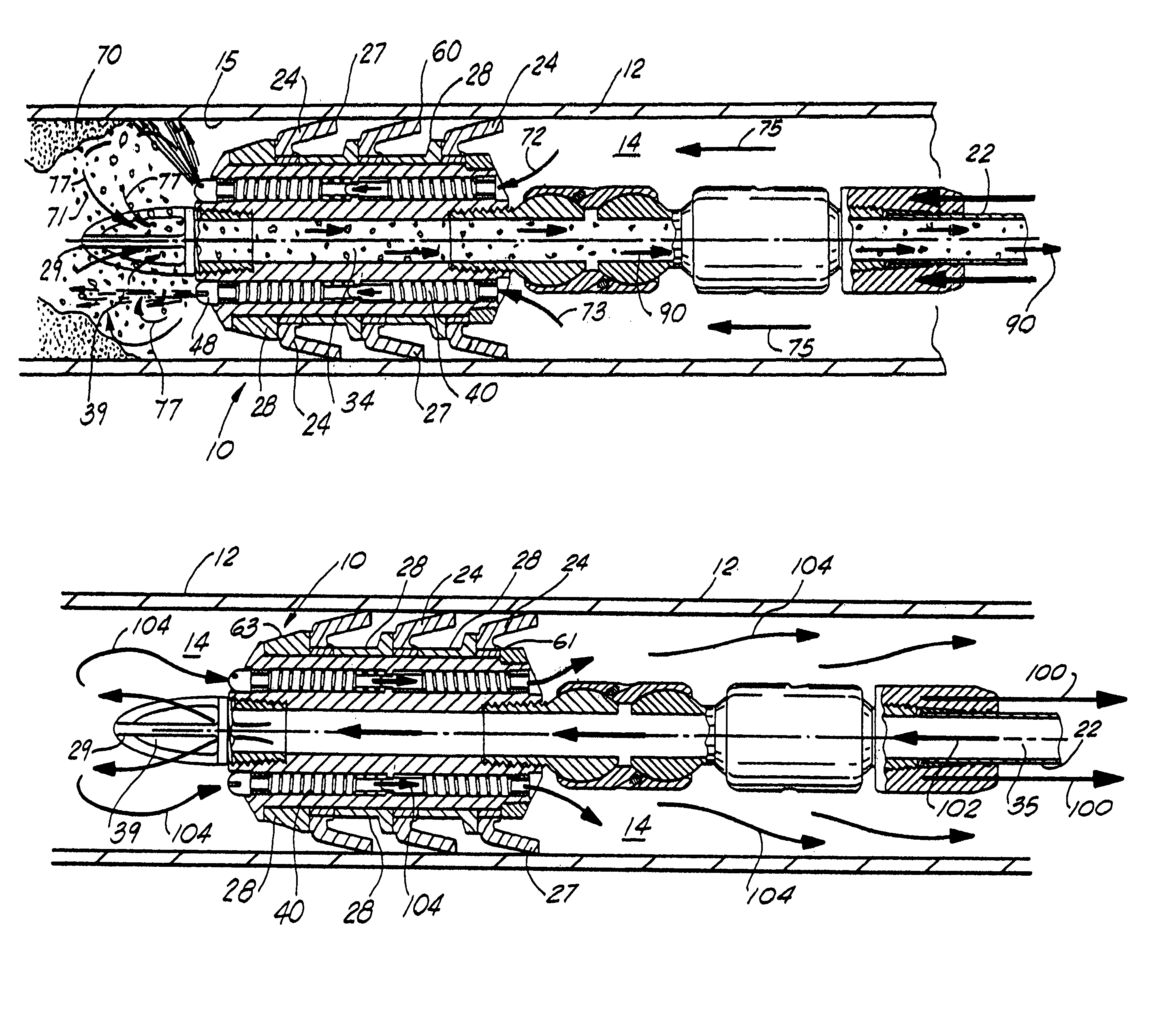
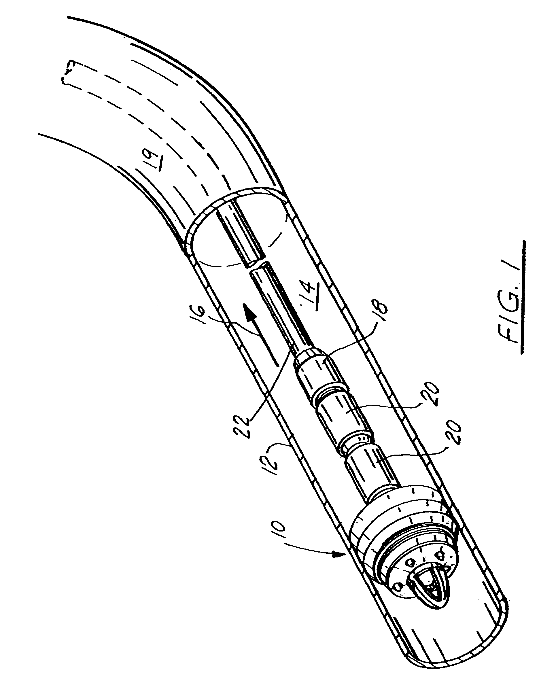
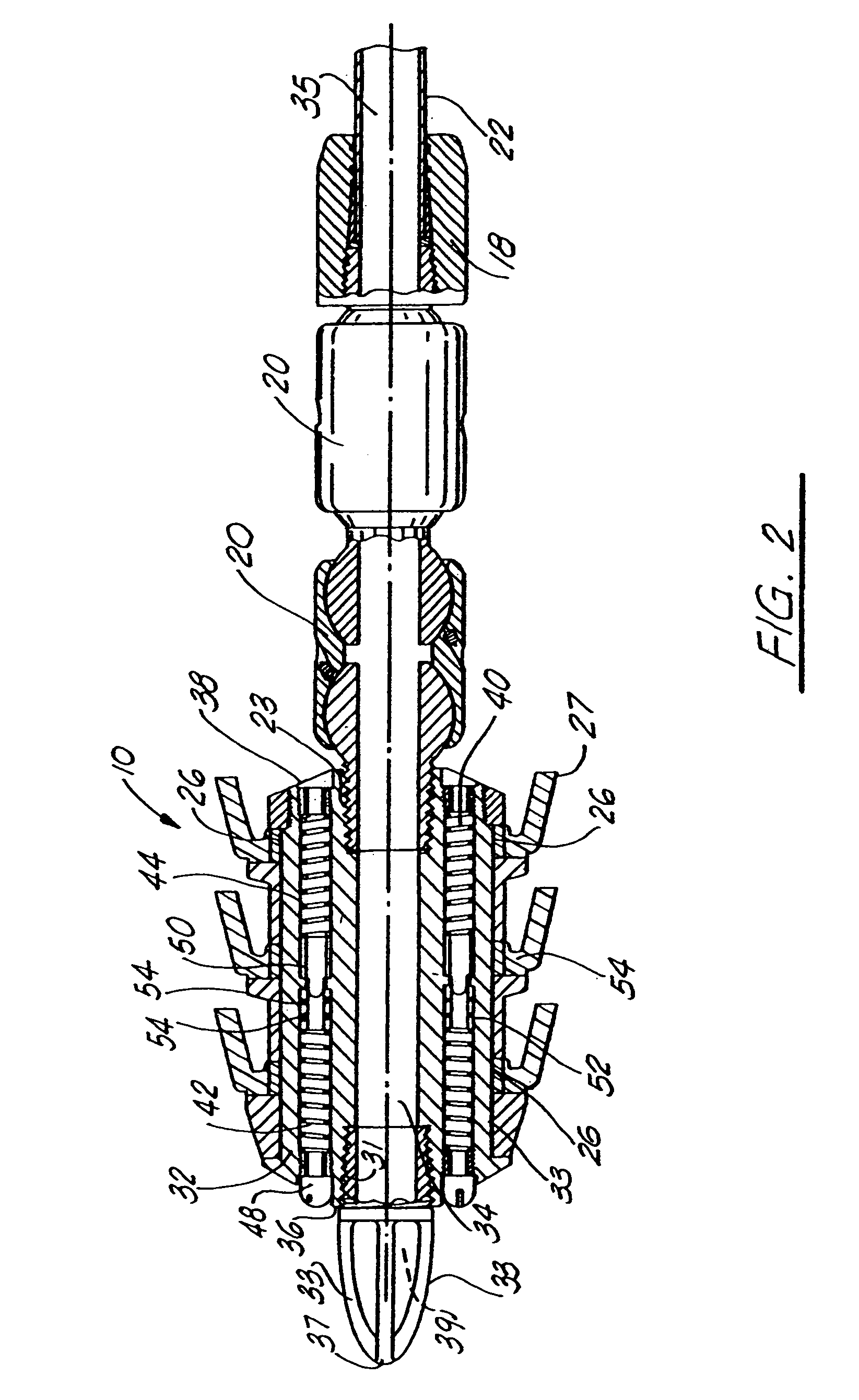
[0046]FIGS. 1–12 illustrate the preferred embodiment of the apparatus of the present invention and the method of using same. As illustrated in overall cutaway view in FIG. 1, there is illustrated the thruster pig apparatus 10, hereinafter commonly referred to as the apparatus 10, which is positioned within a pipeline 12, which is normally a segmented pipeline or casing which has been drilled either vertically, horizontally, or a combination of the two, for a great distance up to fifty or sixty thousand feet, or greater, in order to retrieve hydrocarbons through the bore 14 of the pipeline up to the surface, in the direction of arrow 16. The pipeline, as illustrated, includes a continuous circular wall portion 19 and, as was stated earlier, has a bore 14 therethrough. As seen in FIG. 1, pig apparatus 10 is secured at the end of a length of coiled tubing 22 which is commonly found in the oil and gas industry. Coiled tubing 22, as well known in the art, is a continuous length of somewh...


PUM


Abstract

A retrievable pig apparatus having a substantially cylindrical body portion, the body portion having a central flow bore therethrough, and secured to coiled tubing, including a central fluid flow bore in fluid communication with the interior bore of the coiled tubing; a plurality of flow bores spaced equally apart within the body, with the flow bores allowing fluid flow to be injected at a certain predetermined pressure through the flow bores, so as to be emitted on the front end of the pig for defining a high pressure spray of fluid or the like material to break up blockages of debris in the pipeline, such as paraffin or the like; the debris retrieved through the central bore back into the coiled tubing to be stored in a tank or the like on the surface. There is further included a plurality of flexible cups, spaced apart along the outer wall of the pig body, each cup secured to an interior metallic ring around the body of the pig, with the flexible cups making contact with the wall of the pipeline so as to provide a continuous fluid seal between the wall of the pipeline and the ends of the plurality of flexible cups. Intermediate each cup there is provided a compressible safety ring, which will compress under excess pipeline pressure, thus allowing the fluid to flow past the plurality of flexible cups, reducing the pressure in the pipeline. Further there is provided within the plurality of six flow bores around the interior flow bore, for adjusting the force that is allowed to flow through the plurality of bores in either direction by providing a first and second thruster springs of a pre-determined compressible force for allowing the spring to be compressed and effecting fluid flow therethrough in the direction in which the flow is to travel in the bores.

Description

CROSS-REFERENCE TO RELATED APPLICATIONS[0001]This is a continuation of application Ser. No. 10 / 114,439, filed Apr. 2, 2002, now U.S. Pat. No. 6,651,744 and is a continuation-in-part of U.S. patent application Ser. No. 10 / 068,782, filed Feb. 5, 2002, now U.S. Pat. No. 6,561,280 which is a continuation of U.S. patent application Ser. No. 09 / 185,988, filed Nov. 4, 1998, now U.S. Pat. No. 6,343,657, which claimed priority from provisional patent application Ser. No. 60,066,380 filed on Nov. 21, 1997, entitled “Method and Apparatus of Injecting Coil Tubing Down Pipelines,” and provisional patent application Ser. No. 60 / 067,503 filed on Dec. 4, 1997, entitled “Method and Apparatus of Injecting Coil Tubing Down Piplines,” incorporated herein by reference.STATEMENT-REGARDING FEDERALLY SPONSORED RESEARCH OR DEVELOPMENT[0002]Not applicableREFERENCE TO A “MICROFICHE APPENDIX”[0003]Not applicableBACKGROUND OF THE INVENTION[0004]1. Field of the Invention[0005]The apparatus of the present inventi...

Claims


Application Information

Patent Timeline
Patent Type & Authority Patents(United States)
IPC IPC(8): E21B23/04E21B4/18E21B17/10E21B23/08E21B37/00
CPCE21B4/18E21B17/1014E21B37/00E21B23/08E21B17/1057
Inventor CRAWFORD, JAMES R.
Owner SUPERIOR ENERGY SERVICES LLC
Why Eureka
Try Eureka