Holding and supporting group of a winding spindle in a plastic film winding machine

A technology for supporting components and winding spools, applied in the direction of winding strips, thin material handling, transportation and packaging, which can solve the problems of time loss, incomplete clamping of the mandrel, and inability to ensure axial blocking.

Active Publication Date: 2016-05-18
COLINES SPA
View PDF5 Cites 0 Cited by
  • Summary
  • Abstract
  • Description
  • Claims
  • Application Information

AI Technical Summary

Problems solved by technology

[0004] The first problem that arises with this technique currently used is the loss of time caused by moving the tip and tailstock towards or away from each other in order to load the core and remove the spool being wound
[0005] The second problem concerns vibrations that result from the end support system between the tip and the tailstock not fully buckling the mandrel and not guaranteeing a stable axial block
[0006] Another particular concern concerns possible buckling that occurs in mandrel arrangements between forward facing end supports

Method used


Image

  • Holding and supporting group of a winding spindle in a plastic film winding machine
  • Holding and supporting group of a winding spindle in a plastic film winding machine
  • Holding and supporting group of a winding spindle in a plastic film winding machine

Examples


Embodiment Construction

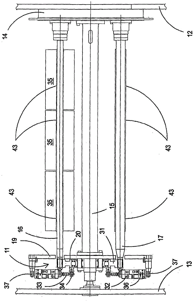
[0024] First refer to figure 1 , figure 1 An upright schematic side view showing a part of the winding machine in the area comprising the holding and supporting assembly 11 of the winding mandrel produced according to the invention is shown.

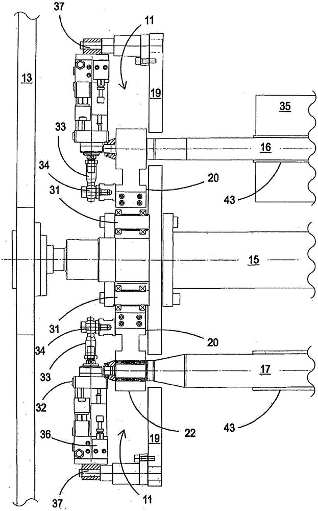
[0025] The holding and supporting assembly 11 is positioned inside two vertical uprights 12, 13 forming the shoulders of the winder. The first upright 12 carries cantilevered on a rotating support plate 14 a central shaft 15 which is supported at the other end corresponding to the second upright 13 .

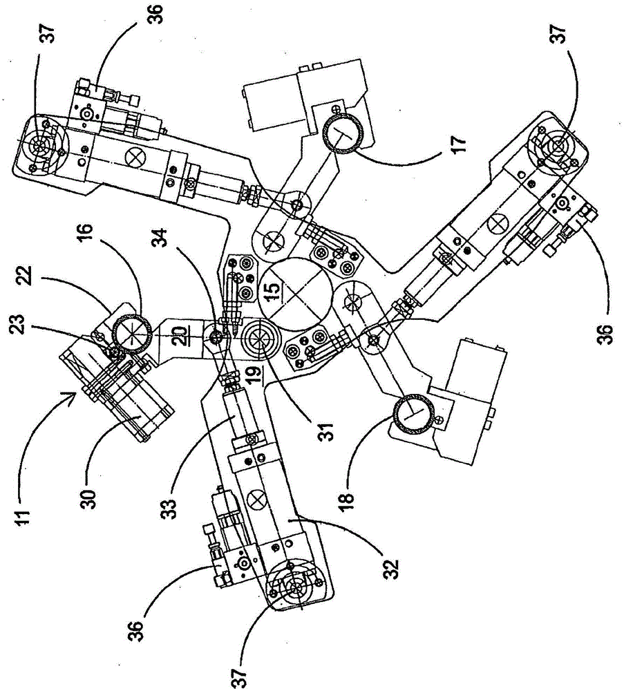
[0026] The plate 14 rotating around the central axis 15 also carries three mandrels 16, 17 and 18, arranged at 120° relative to each other, which completely constitute the winding reel.

[0027] According to the invention, the holding and supporting assembly 11 of the winding mandrel produced according to the invention is associated with the reel.

[0028] Assembly 11 comprises a star plate 19 with three selective support arms of the fr...


PUM


Abstract

A holding and supporting group of a winding spindle in a machine for winding plastic film onto spools, said machine comprising a winding reel positioned between two uprights (12, 13), wherein a first upright (12) carries a rotating plate (14) which cantilever-supports three spindles (16, 17, 18) and a central shaft (15) which complete the winding reel, wherein the central shaft (15) is supported at the other end at the second upright (13), wherein, in correspondence with a free end of the central shaft (15), there is a star-shaped plate (19) with three supporting arms of each free end of the three spindles (16, 17, 18) through a respective toggle lever mechanism (21, 22, 25) driven by an actuator (30) carried on a lever (20) articulated with respect to the star-shaped plate (19), and in turn caused to oscillate between an operative blocking position of the respective spindle (16, 17 or 18) and a rest position for releasing the respective spindle (16, 17, 18) by means of a further actuator (32).

Description

technical field [0001] The invention relates to a holding and supporting assembly for a winding mandrel in a machine for winding plastic film onto rolls. Background technique [0002] Currently, in the field of machines for winding plastic films onto rolls, various support systems for the mandrel present in each winding reel are used. [0003] This support is typically between a tip and tailstock that are moved axially toward or away from each other in order to axially block or release the mandrel for removal of the spool(s). [0004] A first problem arising from this technique currently used is the loss of time caused by moving the tip and tailstock towards or away from each other in order to load the core and remove the wound bobbin. [0005] The second problem concerns vibrations caused by the end support system between the tip and the tailstock not fully gripping the mandrel and not ensuring a stable axial block. [0006] Another particular problem concerns the possibl...

Claims


Application Information

Patent Timeline
Patent Type & Authority Applications(China)
IPC IPC(8): B65H19/22
CPCB65H19/2207B65H2301/41362B65H19/22
Inventor E·佩塞蒂
Owner COLINES SPA
Why Eureka
Try Eureka