Air-bag arrangement and a method of inflating an air-bag

a technology of airbags and airbags, which is applied in the direction of pedestrian/occupant safety arrangements, envelopes/bag making machinery, paper/cardboard containers, etc., can solve the problems of airbag gas loss, clear disadvantage, etc., and achieve the effect of improving protection, prolonging the period of time, and small volum

Inactive Publication Date: 2006-04-11
AUTOLIV DEV AB
View PDF21 Cites 15 Cited by
  • Summary
  • Abstract
  • Description
  • Claims
  • Application Information

AI Technical Summary

Benefits of technology

[0025]In one preferred embodiment of the invention the air-bag, when inflated, provides a uniform degree of protection across a selected area. In a conventional air-bag, which may be divided into a plurality of cells, formed from simply two layers of fabric, there are portions between adjacent cells where seams are located. If part of an occupant of a vehicle strikes the region of the air-bag where a seam is located, the air-bag may provide only a minimum cushioning effect, or an insufficient cushioning effect. In preferred embodiments of the invention, where the chambers of the first chamber set are off-set relative to the chambers of the second chamber set, there is no region where there is simply a seam to be located between the occupant of the vehicle and the vehicle itself. Thus an improved protection is provided.
[0026]Another advantage of an air-bag in accordance with the present invention is that if a window located adjacent the air-bag should break, with parts of the broken window damaging the air-bag, so that the air-bag loses gas, it will only be the set of chambers adjacent the window that lose gas, and the air-bag will still have at least one further set of chambers to provide a reasonable degree of protection for the occupant of the vehicle.
[0027]A further advantage obtained by use of a preferred embodiment of the invention is that the layers of fabric utilised to form the air-bag, especially the intermediate layer or layers may have less coating than is normally provided to ensure that the fabric is substantially gas-tight, or even no coating at all. Because the inflatable element can, if designed appropriately, be subjected to a two-step inflation process, the coating may not be required. This can be advantageous since the coating can be relatively expensive.
[0028]A further advantage is that the chamber sets may be inflated sequentially, thus prolonging the period of time during which the air-bag remains inflated.
[0029]A further advantage is that a first chamber set may have a relatively small volume, thus enabling the air-bag to be deployed swiftly. A second chamber set, constituted by chambers located where protection is required (for example adjacent to the head of an occupant of the vehicle) may then be inflated—for example through a vent from the first chamber set—so that the second chamber set is also inflated within a relatively short period of time.

Problems solved by technology

Parts of a broken window may damage an airbag which is located immediately adjacent that window, and the air-bag may then lose gas and become deflated.
This is clearly disadvantageous.

Method used


Image

  • Air-bag arrangement and a method of inflating an air-bag
  • Air-bag arrangement and a method of inflating an air-bag
  • Air-bag arrangement and a method of inflating an air-bag

Examples


Embodiment Construction

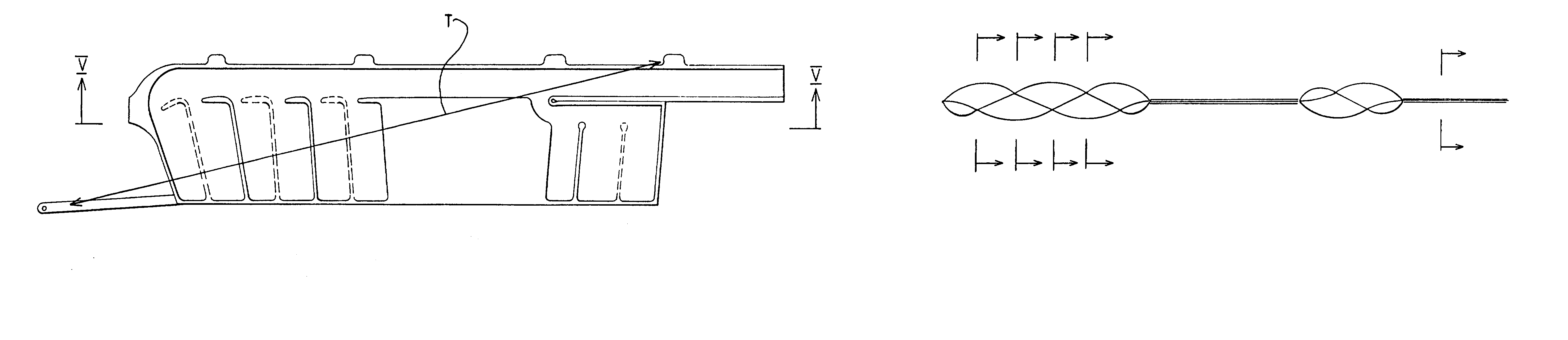
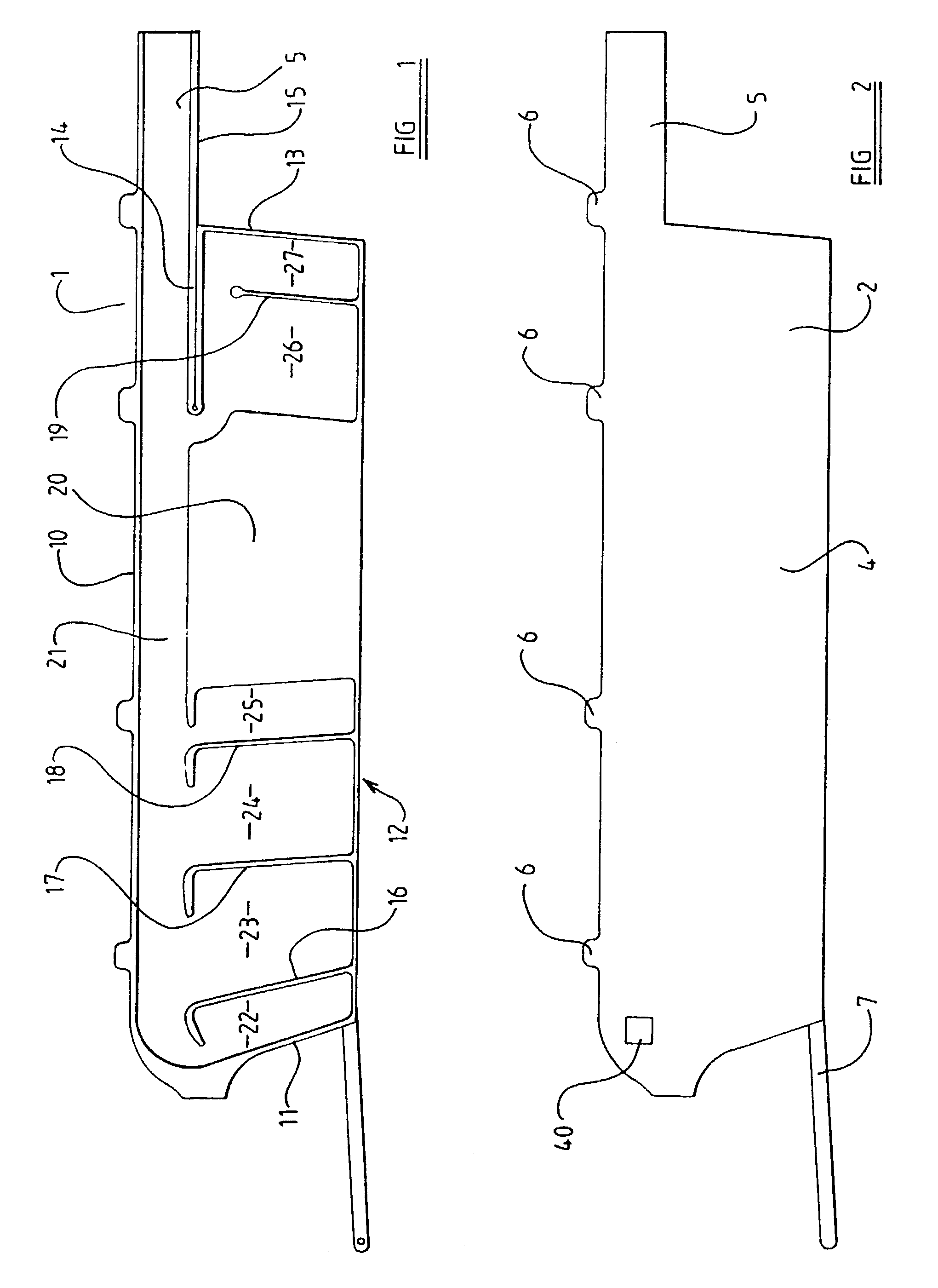
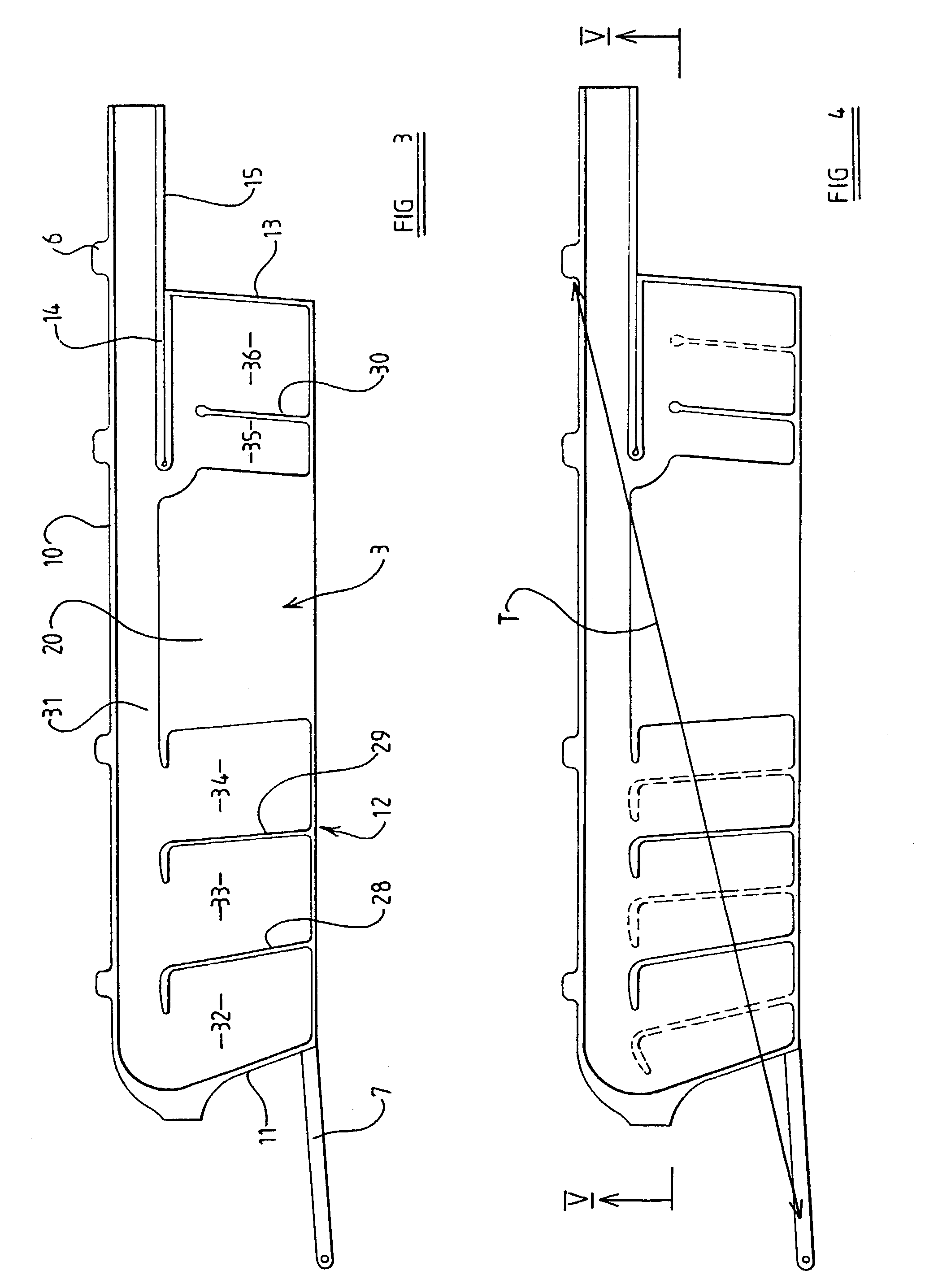
[0039]Referring initially to FIGS. 1, 2 and 3, an air-bag is fabricated from three layers of fabric. A first outer layer 1 of fabric is illustrated in FIG. 1. A second intermediate layer 2 of fabric is illustrated in FIG. 2, and a third outer layer 3 of fabric is illustrated in FIG. 3. The layers of fabric will be located with the two outer layers 1 and 3 on opposite sides of the intermediate layer 2.

[0040]The three layers 1, 2 and 3 each have a substantially identical outer shape. As can be seen most clearly in FIG. 2, each fabric layer comprises a central generally rectangular region 4. This region, as will be described hereinafter, helps define inflatable cells. An extension 5 extends from the top right-hand corner of the generally rectangular region 4 of each fabric layer, as shown in FIG. 2. The extension 5 of each fabric layer, as will become clear hereinafter, helps constitute a gas supply duct.

[0041]A plurality of projections 6 are provided extending across the upper part of...


PUM

PropertyMeasurementUnit
pressureaaaaaaaaaa
tensionaaaaaaaaaa
shapeaaaaaaaaaa

Abstract

An air-bag arrangement provides protection for the occupant of a motor vehicle. The air-bag arrangement incorporates an airbag (50) formed by two layers (51, 52) interconnected to form a first set of chambers (53, 54, 55, 56, 57, 58), having a plurality of elongated substantially parallel chambers. A further fabric layer (61) is connected to one of the two layers (52) forming the main part of the inflatable element to define a second chamber set including two chambers (62, 63). The chambers are off-set from the adjacent chambers (54, 55, 56) defined by the first two layers (51, 52). Apertures (59, 60) provided in the layer (52) allow for the inflation of the second set of chambers (62, 63).

Description

BACKGROUND OF THE INVENTION[0001]The present invention relates to an air-bag arrangement, and more particularly relates to an air-bag arrangement adapted to provide protection for an occupant of a motor vehicle in the event that a side impact or roll-over situation should occur.[0002]It has been proposed previously to provide an air-bag arrangement incorporating an inflatable element initially stored in a recess or housing which extends above the side door openings of a motor vehicle, the inflatable element being adapted to be inflated to occupy a position between the occupant of the vehicle and the side doors of the vehicle. Thus the inflatable element can be considered to constitute an inflatable curtain.[0003]Inflatable elements of this type are disclosed in GB 2,297,950 A. This specification teaches an inflatable element formed of two adjacent sheets of fabric which are interconnected by seams to form a plurality of cells. The configuration of the inflatable element is such that...

Claims


Application Information

Patent Timeline
Patent Type & Authority Patents(United States)
IPC IPC(8): D03D11/00B60R21/233B60R21/16B60R21/232B60R21/2338B60R21/235
CPCB60R21/232B60R21/2338B60R21/235B60R2021/23316B60R2021/23386Y10T428/1307B60R2021/23547Y10T428/1314Y10T428/1317Y10T428/13B60R2021/23504Y10T442/3195Y10T442/3203Y10T442/3211
Inventor DROSSLER, NORBERTKALLHAMMER, JAN-ERIK
Owner AUTOLIV DEV AB
Why Eureka
Try Eureka