Lamp socket

Active Publication Date: 2006-04-11
OSRAM SYLVANIA INC
View PDF3 Cites 29 Cited by
  • Summary
  • Abstract
  • Description
  • Claims
  • Application Information

AI Technical Summary

Benefits of technology

[0004]It is another object of the invention to enhance the seating of bi-pin lamps into an appropriate socket.
[0005]It is yet another object of the invention to lengthen socket life.
[0006]These objects are accomplished, in one aspect of the invention, by the provision of an electrical contact comprising a substantially U-shaped body having an open end and a bight, the U-shaped body comprising a contact port

Problems solved by technology

This condition made it difficult to determine if the bulb was completely seated in the socket.
Additionally, prior contacts often had to be plated to achi

Method used


Image

  • Lamp socket
  • Lamp socket
  • Lamp socket

Examples


Embodiment Construction

[0015]For a better understanding of the present invention, together with other and further objects, advantages and capabilities thereof, reference is made to the following disclosure and appended claims taken in conjunction with the above-described drawings.

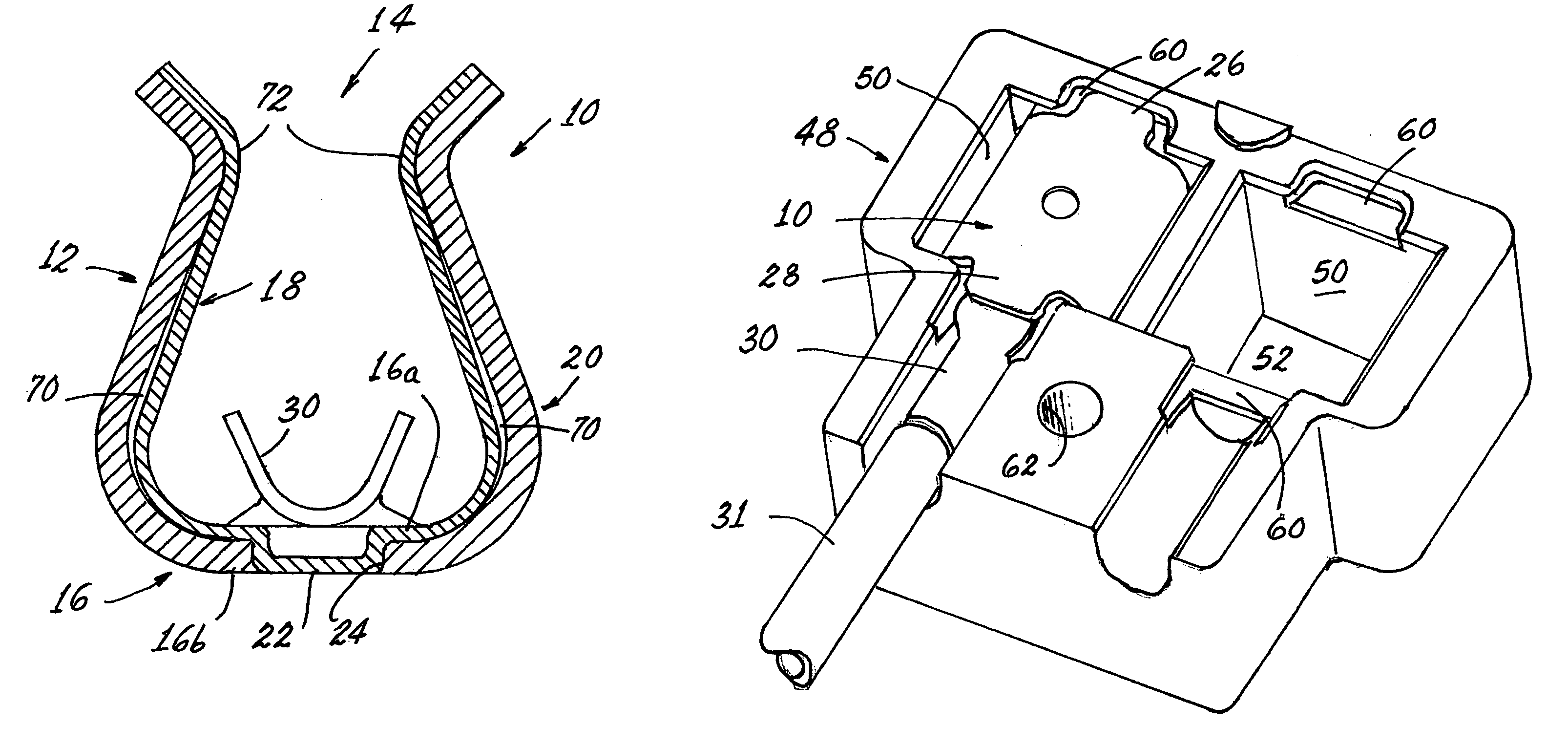
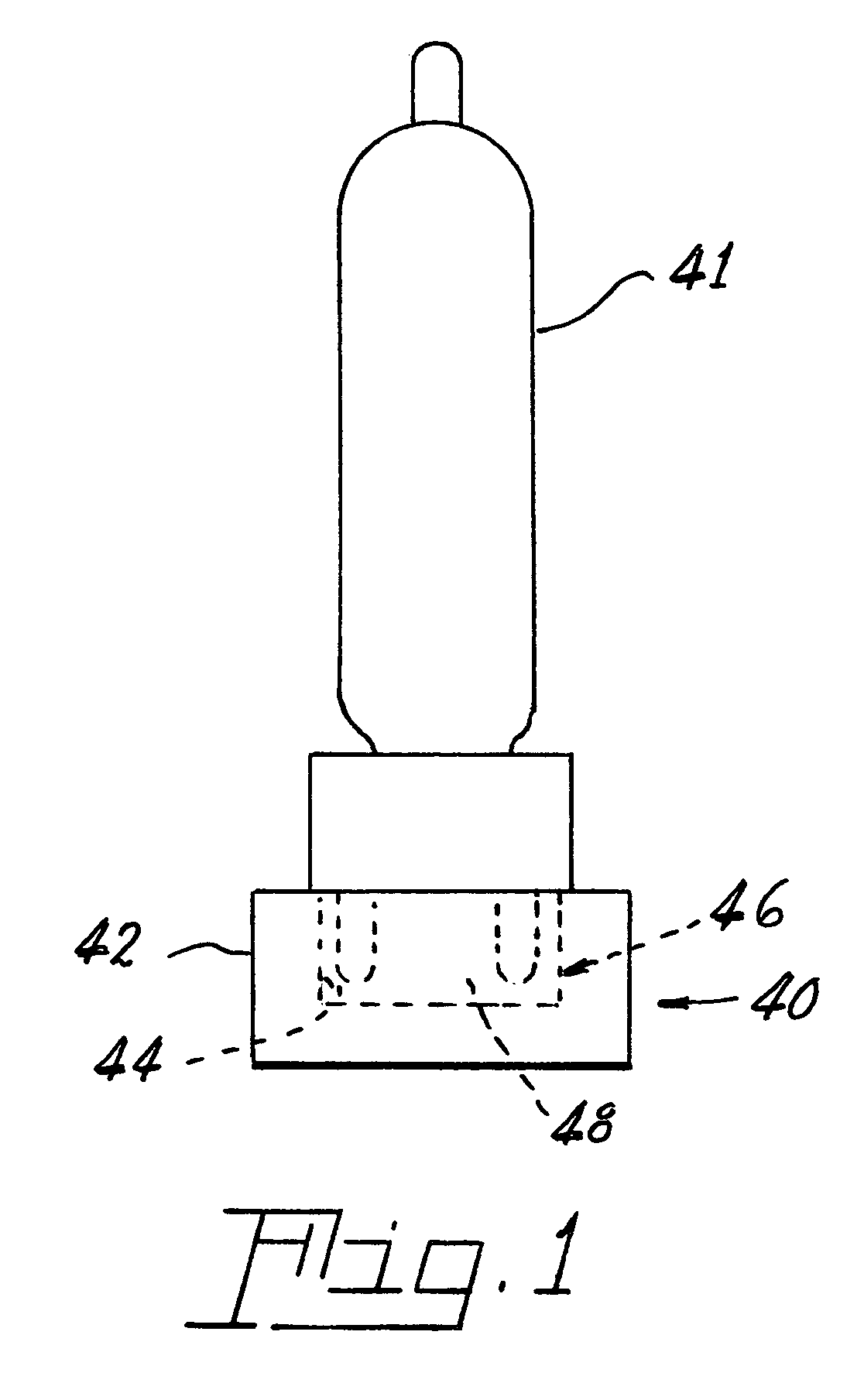
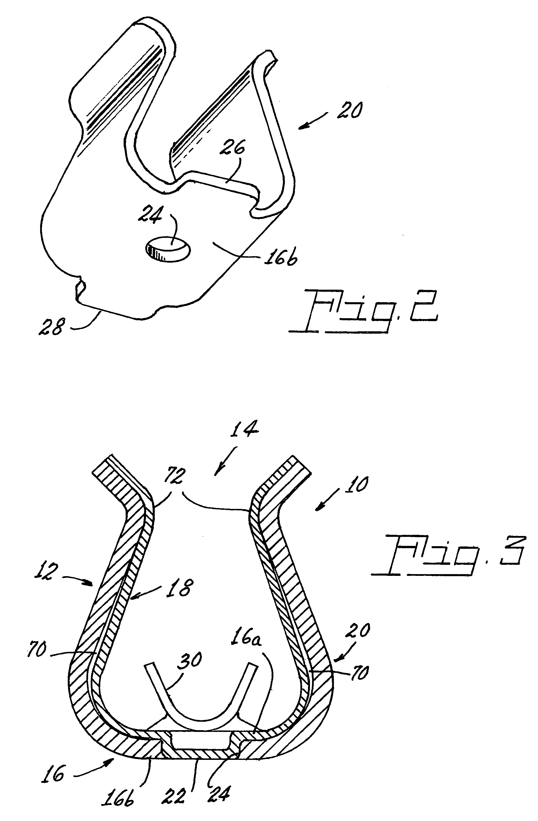
[0016]Referring now to the drawings with greater particularity, there is shown in FIG. 1 a socket 40 for a bi-pin lamp 41. The socket 40 comprises a primary housing 42, formed, for example, from aluminum, and including a receptacle 44. A secondary housing 46 (see FIGS. 4–7) of a suitable ceramic material such as L-3 Steatite is formed to be received in the receptacle 44, the secondary housing 46 having a body 48 with a pair of recesses 50 therein. A floor 52 is provided in the recesses 50 and a pin-receiving aperture 54 is provided in the floor of each of the recesses 50. An electrical contact 10 (see FIG. 3) is positioned in each recess 50. Each electrical contact 10 comprises a substantially U-shaped body 12 having an open end ...


PUM


Abstract

A socket (40) for a bi-pin lamp (41) has a primary housing (42) including a receptacle (44): a secondary housing (46) formed to be received in the receptacle (44), the secondary housing (46) having a body (48) with a pair of recesses (50) therein; a floor (52) in the recesses (50); a pin-receiving aperture (54) in the floor of each of the recesses (50); and an electrical contact (10) positioned in each recess (50), the electrical contact (10) comprising a substantially U-shaped body (12) having an open end (14) and a bight (16), the U-shaped body (12) comprising a substantially U-shaped contact portion (18) formed of a first material nested within a substantially U-shaped contiguous spring portion (20) formed of a second material.

Description

TECHNICAL FIELD[0001]This invention relates to lamp sockets and more particularly to lamp sockets for bi-pin lamps. Still more particularly, it relates to lamp sockets utilizing novel electrical contacts.BACKGROUND ART[0002]Previous lamp sockets for bi-pin lamps have employed tangential contacts, which forced the contact points to change dramatically as the mating lamp pin was inserted, producing and increasing insertion force as the pin was inserted into the socket. This condition made it difficult to determine if the bulb was completely seated in the socket. Additionally, prior contacts often had to be plated to achieve the high conductance levels needed to transmit high current levels to the lamp. The plating was subject to wear, thus limiting the life of the socket.DISCLOSURE OF INVENTION[0003]It is, therefore, an object of the invention to obviate the disadvantages of the prior art.[0004]It is another object of the invention to enhance the seating of bi-pin lamps into an approp...

Claims


Application Information

Patent Timeline
IPC IPC(8): H01J1/00
CPCH01R13/18H01R33/06H01R4/023H01R13/502H01R13/41
Inventor SWANTNER, MICHAEL J.SEYMOUR, DOUGLAS G.SCHOLENO, MICHAEL
Owner OSRAM SYLVANIA INC
Why Eureka
Try Eureka