
Incus replacement prosthesis

a replacement prosthesis and incus technology, applied in the field of incus replacement prosthesis, can solve the problems of poor sound conductive properties and inadequate middle ear prosthesis

Active Publication Date: 2006-04-11
UNIV OF SOUTH FLORIDA
View PDF12 Cites 5 Cited by
  • Summary
  • Abstract
  • Description
  • Claims
  • Application Information

AI Technical Summary

Benefits of technology

[0014]The auditory prosthesis in accordance with the present invention is designed to be positioned such that the pivot element is in contact with the stapes capitulum. The prosthesis further includes a positioning element which is integral to the pivot element. The positioning element serves to adjustably fix the position of the pivot element within the wedge shaped end of the anchoring device. It is within the scope of the present invention that the positioning element be fabricated in a variety of forms, including a threaded screw, a fixed post having a head or cap portion, or any of a plurality of configurations that would be effective in positioning the pivot element within the wedged opening of the anchoring device.
[0016]The anchoring device of the present invention is effective is anchoring the auditory prosthesis to the inner wall of the tympanum of the ear thereby improving the lateral relationship of the stapes capitulum to the malleus. The anchoring device may be designed is a plurality of configurations. In a particular embodiment, the anchoring device includes two anchoring legs that are shaped having compound bends.
[0018]The auditory prosthesis of the present invention may additionally include a vibratory segment of the anchoring device. The vibratory segment of the prosthesis in accordance with the present invention is a part of the anchoring device and is fabricated to be positioned under the malleus thereby reducing the chance that the head of the prosthesis will become trapped between the umbo and the promontory due to changes in the medial positioning of the malleus.
[0021]As such, the present invention provides an improved incus replacement prosthesis that accommodates changes in the lateral relationship of the stapes to the malleus and that is adjustable relative to the medial location of the malleus.

Problems solved by technology

Currently available middle ear prostheses are inadequate to remedy the specific problem of a lateral relationship of the stapes capitulum to the malleus, necessitating a cartilage graft, which has poor sound conductive properties.

Method used


Image

  • Incus replacement prosthesis
  • Incus replacement prosthesis
  • Incus replacement prosthesis

Examples


Embodiment Construction

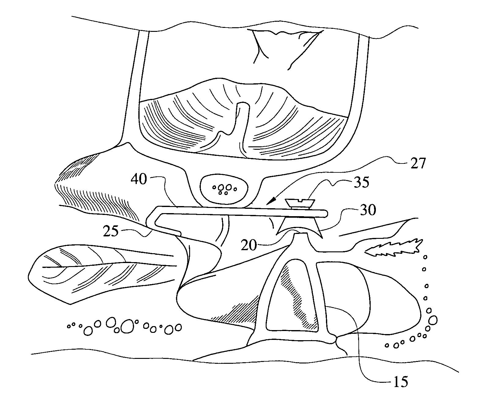
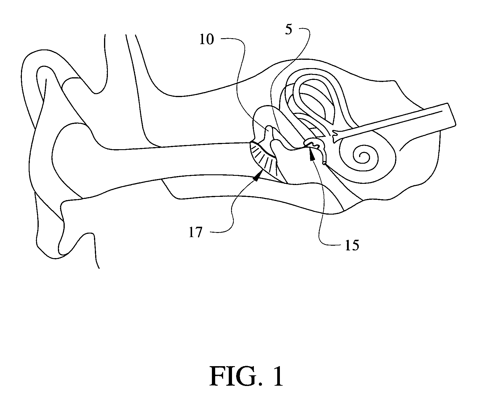
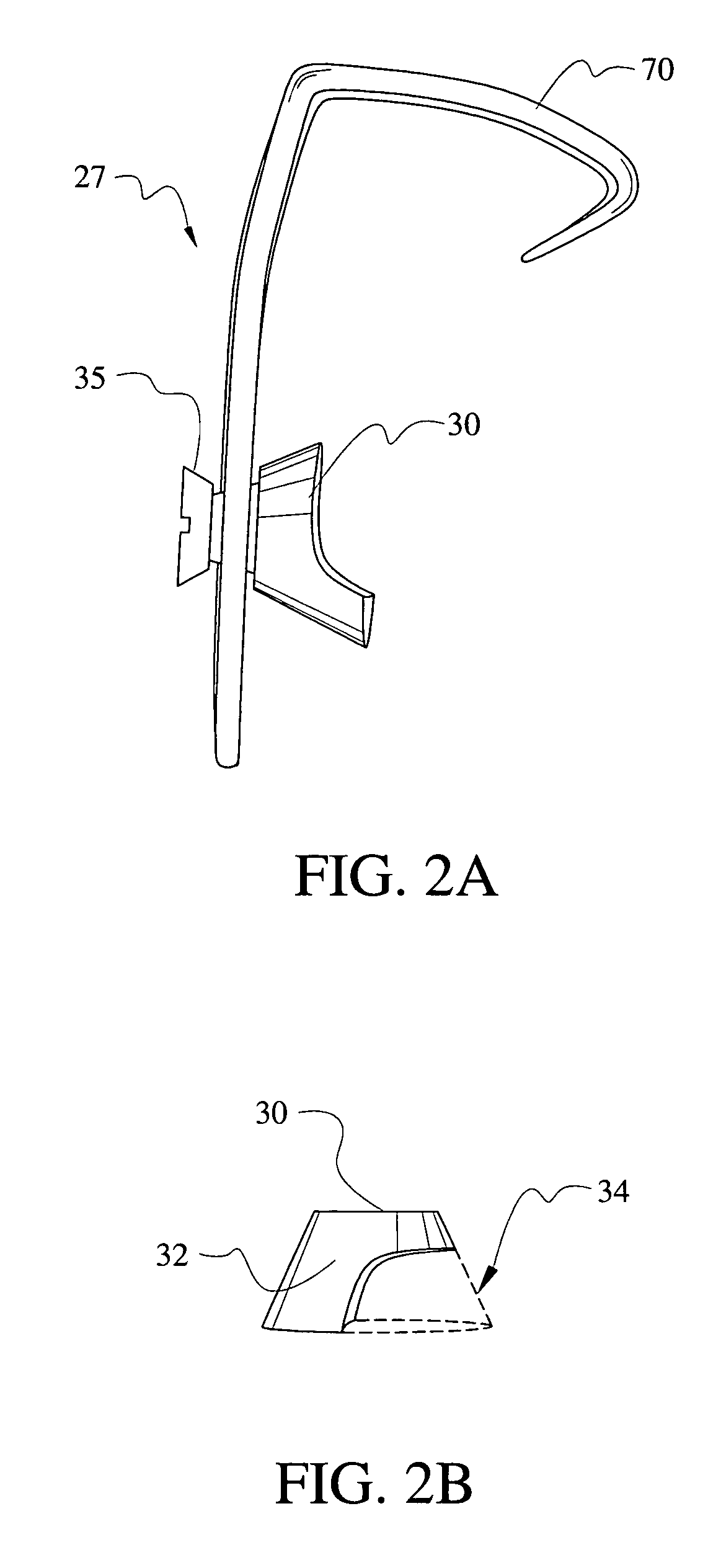
[0033]In accordance with FIG. 1, a human ear is illustrated with the malleus 10, incus 5, stapes 15 and tympanic membrane 17. With reference to FIG. 2A, an exemplary embodiment of the incus replacement prosthesis 27 in accordance with the present invention is shown, including a pivotal element 30, a positioning element 35, and an anchoring device 40. A plurality of variations in design of the elements of the prosthesis are within the scope of the invention, thereby providing an improved incus replacement prosthesis that accommodates changes in the lateral relationship of the stapes to the malleus and that is adjustable relative to the medial location of the malleus.

[0034]As illustrated with reference to FIG. 2B, the adjustable pivot element 30 may be fabricated of a solid material 32 have the shape of an upside down cup and further including a cutaway portion 34, thereby creating a curved surface upon which the pivot element is in contact with the stapes capitulum. The curved surfac...


PUM


Abstract

The present invention provides a device to restore hearing to individuals who have a discontinuity in the middle ear sound conductive mechanism. The device in accordance with the present invention addresses a specific problem arising often in middle ear surgery. Currently available middle ear prostheses are inadequate to remedy the specific problem of a lateral relationship of the stapes capitulum to the malleus, thereby necessitating a cartilage graft resulting in poor sound conductive properties. The present invention provides a middle ear prosthesis that solves the problems associated with the lateral relationship of the stapes capitulum to the malleus.

Description

CROSS REFERENCE TO RELATED APPLICATIONS[0001]This application claims priority to U.S. Provisional Patent Application No. 60 / 533,469 filed Dec. 30, 2003 and U.S. Provisional Patent Application No. 60 / 535,146 filed Jan. 8, 2004, both filed by the same inventor and both entitled: “Promotory Anchored Incus Replacement Prosthesis.”BACKGROUND OF INVENTION[0002]The present invention addresses a specific problem arising often in middle ear surgery. Numerous causes contribute to ossicular discontinuity including chronic ear disease, congenital aplasia and hypoplasia, and traumatic injury. The location of the incus predisposes it to damage from cholesteatoma. The long process of the incus is most frequently fractured in cases of temporal bone trauma. Additionally, the incus is the ossicle which is most likely to be congenitally hypoplastic or even absent. For the above reasons, ossicular discontinuity secondary to an incus deficiency is one of the most commonly encountered conditions requirin...

Claims


Application Information

Patent Timeline
Patent Type & Authority Patents(United States)
IPC IPC(8): A61F2/18
CPCA61F2/18A61F2002/183
Inventor BOYEV, K. PAUL
Owner UNIV OF SOUTH FLORIDA
Learn More