Thermal fixing device and image forming device provided with the same

a technology of thermal fixing device and image forming device, which is applied in the direction of electrographic process apparatus, instruments, printing, etc., can solve the problems of not being economical in terms of sensor, frequent exchange of thermal fixing device, etc., and achieve the effect of avoiding wasteful use of temperature sensor uni

Inactive Publication Date: 2006-04-11
BROTHER KOGYO KK
View PDF19 Cites 13 Cited by
  • Summary
  • Abstract
  • Description
  • Claims
  • Application Information

AI Technical Summary

Benefits of technology

[0007]It is an object of the present invention to overcome the above-described problems and to provide an improved thermal fixing device capable of only replacing a thermal fixing unit with a new thermal fixing unit while a temperature sensor unit is still installing in a main casing of an image forming device, thereby avoiding wasteful use of the temperature sensor unit.

Problems solved by technology

In this case, the heat roller and the pressure roller must be frequently replaced by new rollers due to frictional wear as a result of pressure contact with each other, whereas the temperature sensor and particularly the non contact type sensor needs not be replaced frequently, because the latter can provide a prolonged service life because of out of contact from the heat roller.
Therefore, in the conventional arrangement, frequent exchange of the thermal fixing device is not economical in terms of the sensor.

Method used


Image

  • Thermal fixing device and image forming device provided with the same
  • Thermal fixing device and image forming device provided with the same
  • Thermal fixing device and image forming device provided with the same

Examples


first embodiment

[0020]An image forming device according to the present invention will be described with reference to FIGS. 1 through 6. The embodiment pertains to a laser printer.

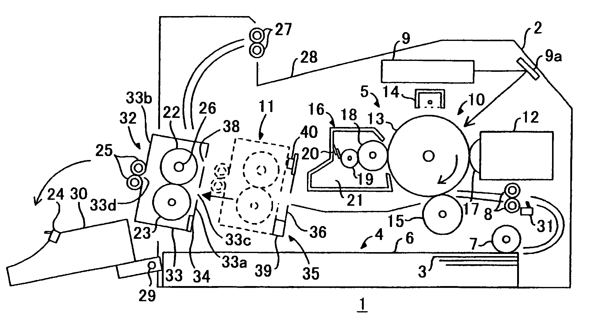
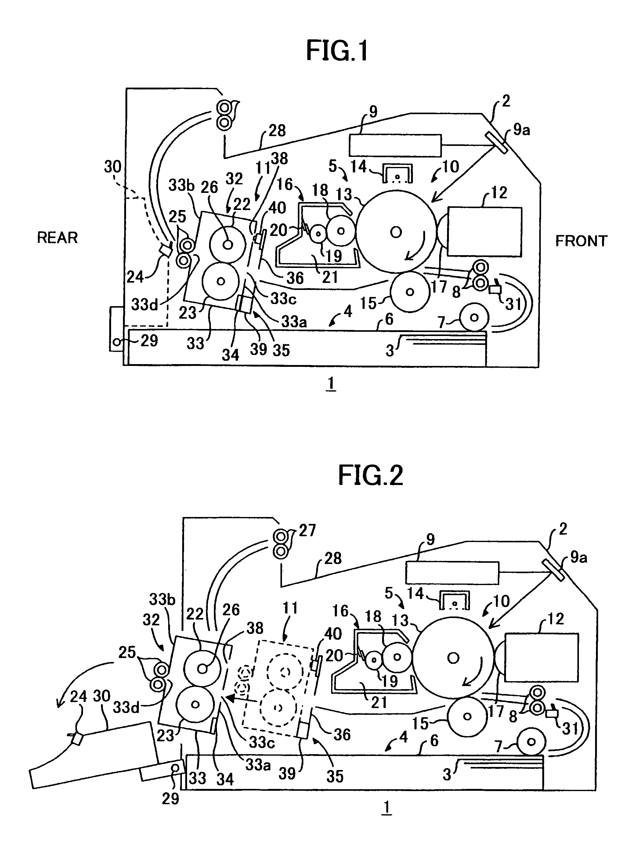
[0021]In FIG. 1, a laser printer 1 includes a main casing 2 in which a feeder unit 4 for supplying a sheet 3 and an image forming unit 5 for forming image on the sheet 3 are disposed. The feeder unit 4 includes a sheet supply tray 6, a sheet supply roller 7, a register roller 8 and a register sensor 31. The sheet supply tray 6 is detachably installed at a bottom of the main casing 2. The sheet supply roller 7 is disposed above an outlet end of the sheet supply tray 6. The register roller 8 is disposed downstream of the sheet supply roller 7 in a sheet feeding direction. The register sensor 31 is disposed immediately upstream of the register roller 8.

[0022]The sheet supply tray 6 accumulates therein a stack of cut sheets 3, and an uppermost sheet 3 of the sheet stack is supplied toward the register roller 8 by the rotation ...

third embodiment

[0067]FIG. 8 shows a thermal fixing device according to a A temperature sensor 241 does not provide a conduit 42 of the foregoing embodiments, and a sensor cover 257 is pivotally supported to the main casing 2 by a pivot shaft 260 for closing the detection window 47 of the light receiving portion 45 when the thermal fixing unit 232 is moved away from the temperature sensor 241.

[0068]More specifically, the sensor cover 257 is in a bent shape having a major arm section 258 adapted for covering the detection window 47 and an abutment arm section 259 integral with the major arm section 258. The major arm section 258 is directed vertically because of its gravity when the major arm 258 completely covers the detection window 47. A casing 233 has an outer arm 261 whose free end is abuttable onto a free end of the arm section 259 when the thermal fixing unit 232 is assembled to the main casing 2. The casing 233 is formed with an elongated hole 262 opened at its front end face for receiving ...


PUM


Abstract

A thermal fixing device is provided in an image forming device having a main casing. The thermal fixing device includes a thermal fixing unit provided with a heat roller and a pressure roller for heatingly fixing a visible image onto a sheet, and a temperature sensor unit for detecting a temperature of the thermal fixing unit. The temperature sensor unit is mounted to the main casing, and the thermal fixing unit is detachably mounted to the temperature sensor unit.

Description

BACKGROUND OF THE INVENTION[0001]The present invention relates to a thermal fixing device and an image forming device provided with the fixing device.[0002]In an image forming device such as a laser printer, a thermal fixing device including a heat roller and a pressure roller is provided for thermally fixing a toner image onto a sheet. In the thermal fixing device, the toner image which has been transferred onto the sheet is thermally fixed to the sheet when the sheet passes through a nip between the heat roller and the pressure roller.[0003]Generally, the heat roller installs therein a heater such as a halogen lamp, and a temperature sensor is provided for detecting a surface temperature of the heat roller. The fixing temperature can be maintained at a constant temperature by ON / OFF control to the heater based on the detection of the surface temperature by the temperature sensor.[0004]Known as the temperature sensor are a contact type sensor such as a thermistor which is in direct...

Claims


Application Information

Patent Timeline
Patent Type & Authority Patents(United States)
IPC IPC(8): G03G15/20B41J11/00G03G21/16
CPCB41J11/002G03G15/2053G03G21/1685
Inventor YOKOI, KATSUYUKI
Owner BROTHER KOGYO KK
Why Eureka
Try Eureka