
Method for manufacturing electronic device using plasma reactor processing system

A plasma reaction and processing system technology, which is applied in the field of manufacturing electronic devices using a plasma reaction furnace processing system, can solve problems such as high pressure and fluctuations, and achieve the effects of saving power, reducing waiting time, and reducing costs

Inactive Publication Date: 2009-09-02
ORMON CORP +1
View PDF3 Cites 5 Cited by
  • Summary
  • Abstract
  • Description
  • Claims
  • Application Information

AI Technical Summary

Problems solved by technology

[0007] On the other hand, even if a pressure control type flow regulator is used as the flow regulator, when the flow rate is changed by providing a new flow rate regulator for each component gas flow rate, even if there is pressure in the discharge pipe of the gas in the processing box The controller also has the problem of relatively large pressure fluctuations in the processing box

Method used


Image

  • Method for manufacturing electronic device using plasma reactor processing system
  • Method for manufacturing electronic device using plasma reactor processing system
  • Method for manufacturing electronic device using plasma reactor processing system

Examples


Embodiment Construction

[0071] Hereinafter, preferred embodiments of a method of manufacturing an electronic device using a plasma reactor processing system according to the present invention will be described in detail with reference to the accompanying drawings.

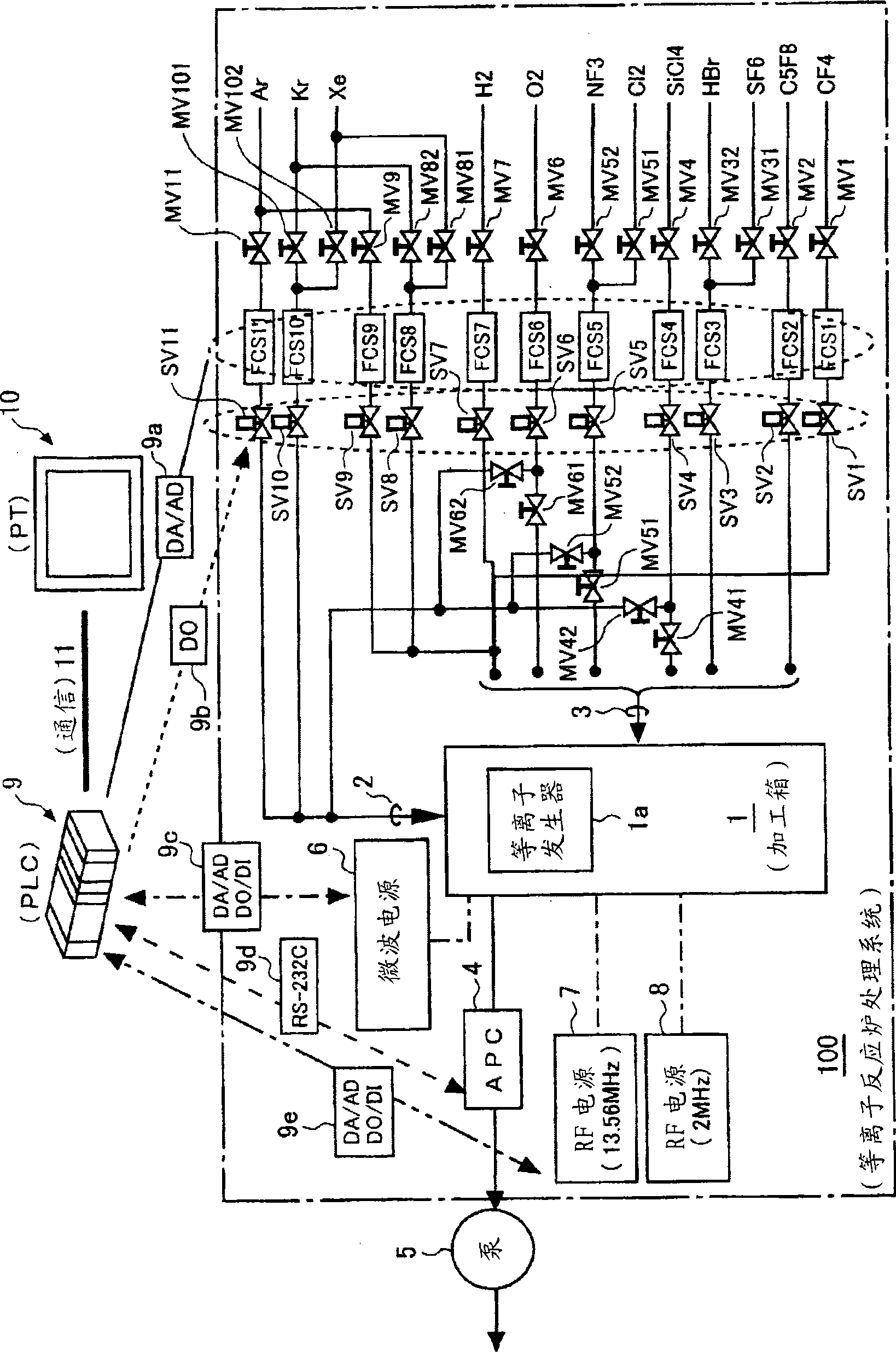
[0072] figure 1 A diagram showing the overall structure of the plasma reactor system. As shown in the figure, the plasma reactor processing system 100 has: a processing box 1 with a built-in plasma generator 1a; 1 connected inert gas supply pipeline; connect one or more than two processing gas sources (in this example, H 2 , O 2 、NF 3 , Cl 2 、SiCl 4 , HBr, SF 6 、C 5 f 8 、CF 4 ) are respectively connected with the processing gas supply pipeline of the processing box 1;

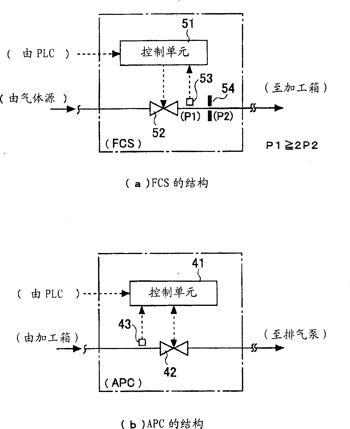
[0073] Each of the inert gas supply pipe and the process gas supply pipe has a flow control system (hereinafter referred to as FCS) functioning as a pressure control type flow regulator, and the pressure control type flow regulator has the following functions. T...


PUM


Abstract

To enable change of a concentration of atmosphere in a process chamber and realize a plasma reaction process required for manufacturing a liquid crystal device and a semiconductor device with a high yield at a low cost.A new flow rate setting value given to a pressure control type flow rate adjusting device of each constituent gas is a value obtained by calculating back from the process gas concentration after an estimated change under the condition that the total flow rate value is identical before and after the concentration change.A pressure controller of an exhaust pipe is switched from a pressure setting mode to a valve open setting mode only for a predetermined small time from the modification start and receives a valve open setting value obtained experimentally so as to mitigate the pressure fluctuation immediately after the change.

Description

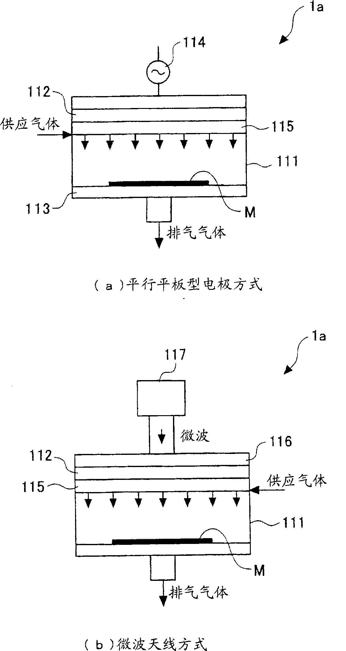
technical field [0001] This invention relates to a manufacturing method of an electronic device using a plasma reactor processing system suitable for manufacturing electronic devices such as liquid crystal devices and semiconductor devices. Background technique [0002] This plasma reaction furnace processing system has: a processing chamber (process chamber) with a built-in plasma generator (for example, a parallel plate electrode method, a microwave antenna method, etc.); , Kr, Xe, etc.) respectively connected to the processing box of the inert gas supply pipeline; one or more than two kinds of processing gas sources (for example, H 2 , O 2 、NF 3 , Cl 2 、SiCl 4 , HBr, SF 6 、C 5 f 8 、CF 4 etc.) the supply pipes of the processing gas respectively connected with the processing box; and the discharge pipes of the gas in the box connecting the processing box and the exhaust pump. [0003] In each of the supply pipes of each inert gas and each process gas, there is a fl...

Claims


Application Information

Patent Timeline
Patent Type & Authority Applications(China)
IPC IPC(8): H01L21/3065B01J19/08H01L21/31C23C16/455
Inventor 井上善规森下贞治大见忠弘
Owner ORMON CORP
Learn More