Data transfer device

a data transfer and data technology, applied in data switching networks, instruments, frequency-division multiplexes, etc., can solve problems such as the defect of increasing the cost of the device, and achieve the effects of reducing the wasteful use of the device, preventing the wasteful use of the band, and increasing the cost of manufacturing the devi

Inactive Publication Date: 2005-07-28
FUJITSU LTD
View PDF10 Cites 5 Cited by
  • Summary
  • Abstract
  • Description
  • Claims
  • Application Information

AI Technical Summary

Benefits of technology

[0017] The use of the store-and-forward method can obviate the former of the above causes, and hence the problem can be solved. Instead, however, there must be used a communication path exhibiting a large processing delay even when the error does not occur, and besides each of the devices requires a memory for accumulating the frames, resulting in a defect of increasing a cost for the device.
[0019] The present invention, in view of the problems inherent in the prior arts, adopts the means for solving the latter of the causes given above by using the cut-through method. Namely, it is an object of the present invention to provide a transmission device and a transmission method that are capable of preventing a wasteful use of bands on a network due to an error frame or reducing a wasteful use of a throughput of a destination host by enabling the error frame to be discarded midways of being transmitted.
[0047] With these configurations, according to the present invention, when transferring the data by the cut-through method, each of the data transfer devices building up the communication paths executes the discard process of discarding the error-occurred data frame (error frame) on the basis of the control frame, thereby enabling the error frame to be discarded midways of being transmitted and a wasteful use of the bands of the communication paths to be prevented or a wasteful use of the throughput of the destination host to be reduced.

Problems solved by technology

Instead, however, there must be used a communication path exhibiting a large processing delay even when the error does not occur, and besides each of the devices requires a memory for accumulating the frames, resulting in a defect of increasing a cost for the device.

Method used


Image

  • Data transfer device
  • Data transfer device
  • Data transfer device

Examples


first embodiment

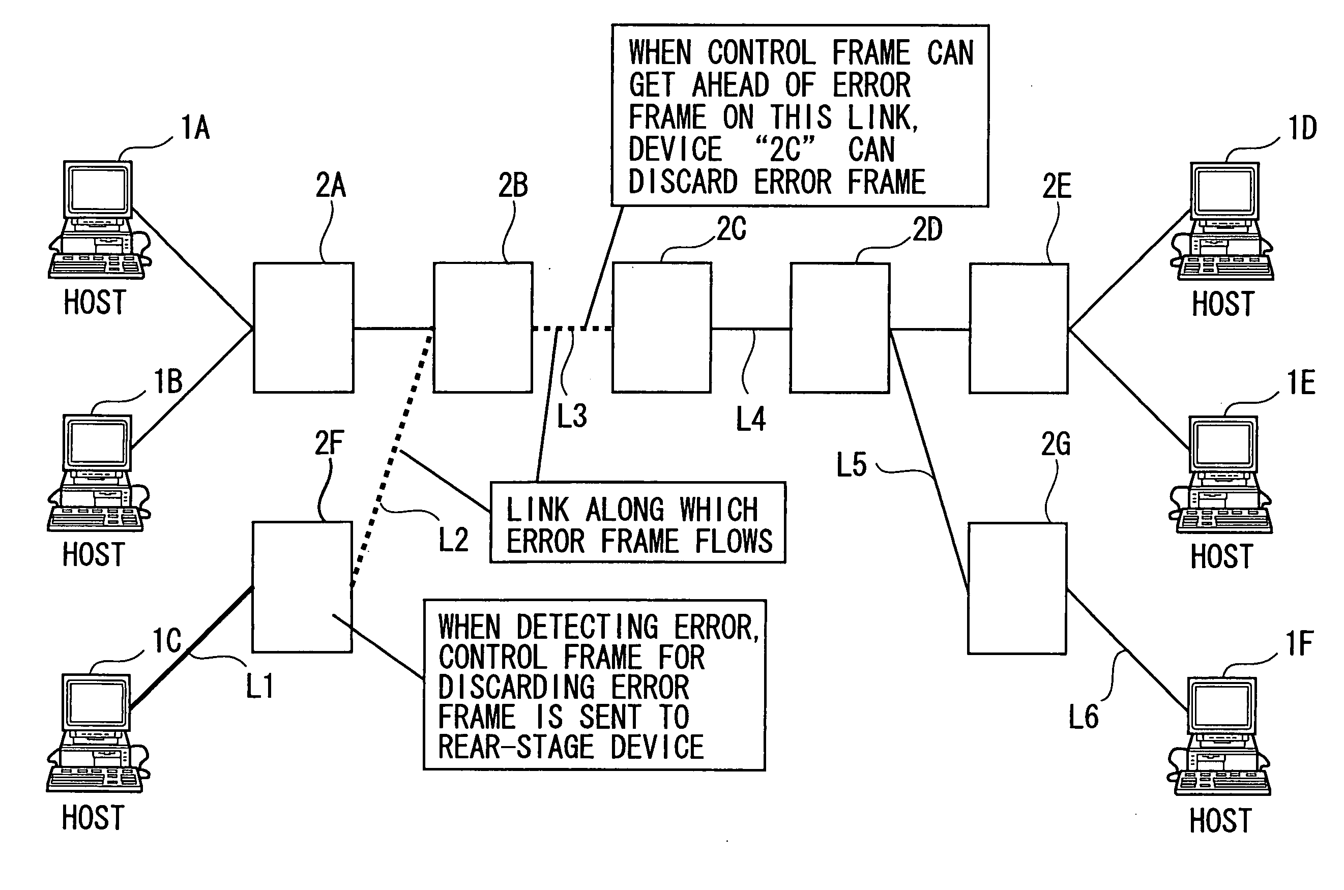
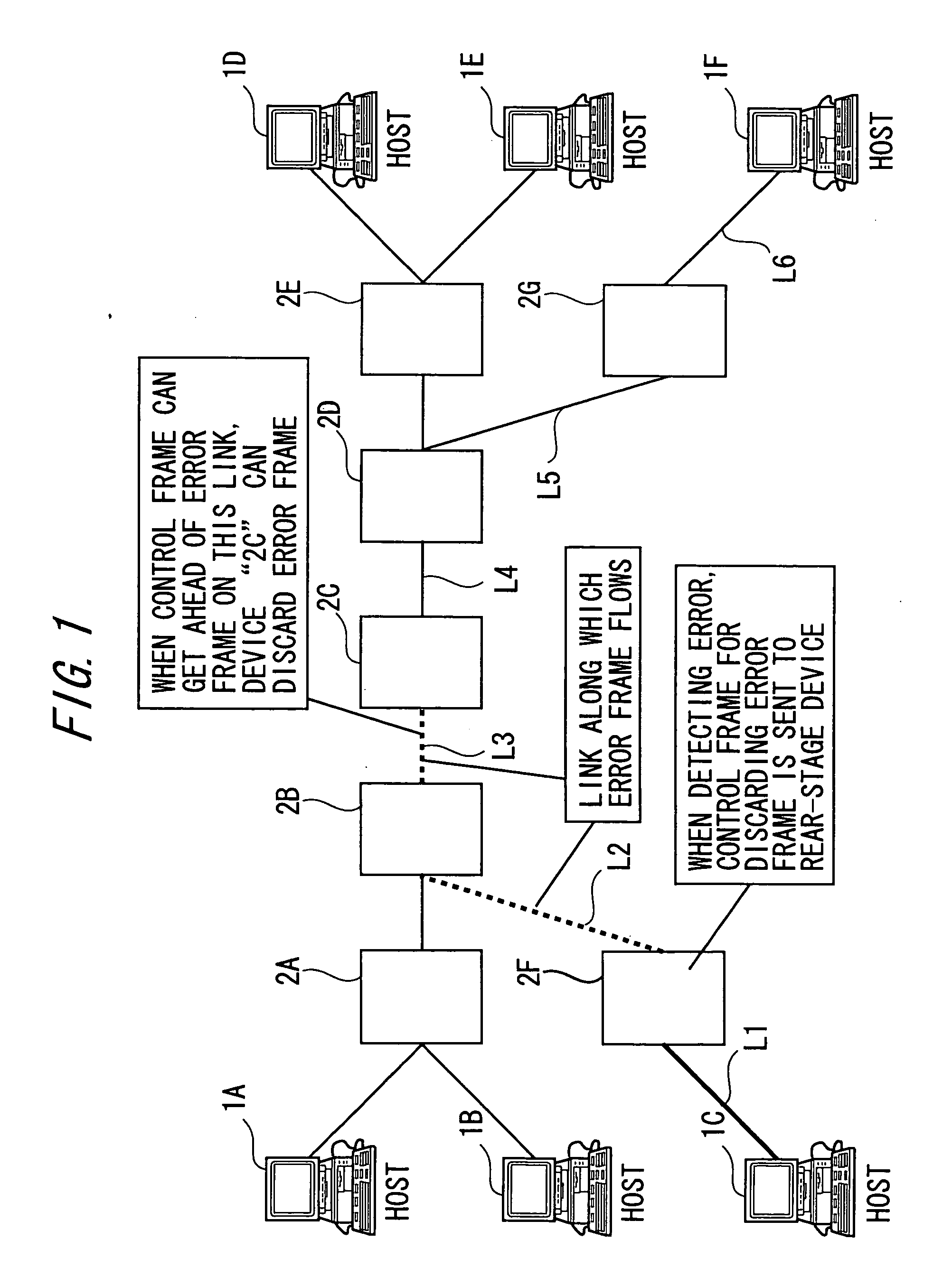
[0061]FIG. 1 is a block diagram showing a network architecture adopting a switch hub (corresponding to a data transfer device) by way of one embodiment of the present invention.

[0062] In the network according to the first embodiment, a plurality of hosts 1A through 1F are connected via a plurality of switching hubs 2A through 2G.

[0063] Whole Configuration of Data Transfer Device

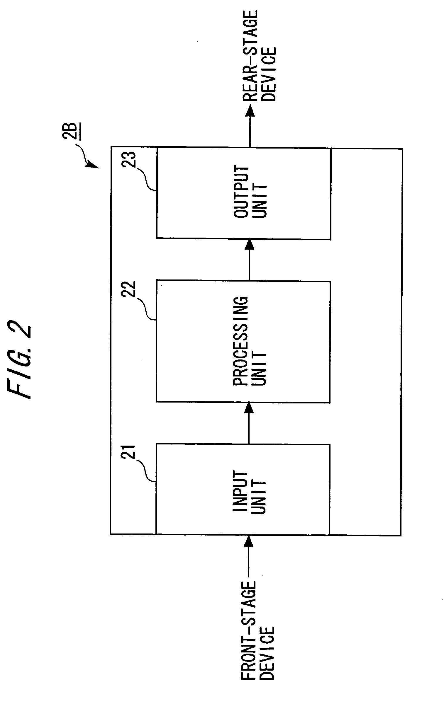
[0064]FIG. 2 shows a whole configuration of a switching hub 2A according to the present invention.

[0065] As shown in FIG. 2, the switching hub 2B in the first embodiment is constructed of an input unit 21, a processing unit 22 and an output unit 23, wherein the data are transferred by a cut-through method.

[0066] The input unit 21 accepts a data frame and a control frame that are outputted from a device (which is the switching hub 2F in this example) at a front stage, and outputs, after converting the data frames into a format processable by the processing unit 22, these converted frames to the processing...

second embodiment

[0117]FIG. 8 is a block diagram showing a processing unit in a second embodiment of the present invention.

[0118] The second embodiment is different from the first embodiment in terms of a point of providing and storing an error table (corresponding to an error storage module) with information about the control frame sent when detecting the error and thus preventing the control frame from being dually transmitted. Other configurations are substantially the same, and hence the repetitive explanations are omitted by marking the same components with the same numerals and symbols, and so on.

[0119] In the second embodiment, as shown in FIG. 9, the error detection unit 36 of the switching hub 2B, when detecting the error in step 13, writes the identification number of the error-detected data frame in an error table 60, and makes a record of detecting the error within the present device and transmitting the control frame to the rear-stage device (S21).

[0120] Further, when the control fra...

third embodiment

[0122]FIG. 10 is a block diagram showing a processing unit in a third embodiment of the present invention.

[0123] The third embodiment is a more improved version of the configuration of the second embodiment, wherein a different point is that a discard target frame table is searched through when detecting the error and, if an error frame has already been recorded, the control frame is not assembled. Other configurations are substantially the same, and hence the repetitive explanations are omitted by marking the same components with the same numerals and symbols, and so on.

[0124] In the third embodiment, as shown in FIG. 11, the error detection unit 36 of the switching hub 2B, when detecting the error in step 12, before assembling the control frame, judges by searching through the discard target frame table whether an identification number of the transmitted data frame has been already recorded or not (S31), and, if already recorded, inhibits the control frame form being assembled. ...


PUM


Abstract

A data transmission apparatus and a data transmission method for receiving an input of control frame and a data frame, transmitting or discarding the data frame according to the control frame input, outputting the control frame, and outputting the data frame which has been transmitted. This enables discarding of an error frame in the middle of transmission, thereby preventing waste of a band on the network or the waste of the destination host processing ability by the error frame.

Description

BACKGROUND OF THE INVENTION [0001] The present invention relates to a data transfer device such as a switching hub, etc. for transferring data across a network such as Ethernet, etc. [0002] A frame transfer method in the Ethernet (registered trademark) can be roughly classified into two methods. One method is a store-and-forward method, and the other is a cut-through method. [0003] In the case of the store-and-forward method, the data transfer device temporarily stores a memory with all of received frames and transmit the frame to a next device. [0004] On the other hand, in the case of the cut-through method, the data transfer device executes a process of determining a device to which the frame should be transferred (forwarded) next at a point of time when receiving MAC DA (Media Access Control Destination Address) contained in the frame, and starts transferring the frame if transferable at a point of time when determining the transfer target device (refer to Patent document 1, para...

Claims


Application Information

Patent Timeline
Patent Type & Authority Applications(United States)
IPC IPC(8): G01R31/08H04L12/46H04L47/32
CPCH04L45/06H04L45/40H04L49/555H04L49/351H04L47/10
Inventor SAITO, MASAHIRO
Owner FUJITSU LTD
Why Eureka
Try Eureka